Thermally-assisted magnetic recording head including first and second cladding sections having different characteristics

a technology of magnetic recording head and cladding section, which is applied in the manufacture of head surface, data recording, instruments, etc., can solve the problems of difficult suppression of cladding section agglomeration, deterioration of recording performance, and easy agglomeration of plasmon generators, etc., and achieves superior recording performance.

Active Publication Date: 2014-07-01
TDK CORPARATION
View PDF17 Cites 8 Cited by
  • Summary
  • Abstract
  • Description
  • Claims
  • Application Information

AI Technical Summary

Benefits of technology

[0016]In the thermally-assisted magnetic recording head, the head gimbal assembly, the head arm assembly, and the magnetic recording unit according to the respective embodiments of the invention, out of the cladding layer allowing the plasmon generator to be embedded therein, the first cladding section located on the side close to the air-bearing surface has the thermal expansion coefficient larger than the thermal expansion coefficient of the second cladding section located on the side far from the air-bearing surface. In this case, at the time of recording, even if thermal expansion occurs in the vicinity of the air-bearing surface due to high temperature, stress is less likely to be applied to a forward section of the plasmon generator. Accordingly, since the forward section of the plasmon generator is less likely to be agglomerated, superior recording performance is obtainable.

Problems solved by technology

As a result, large stress is applied to the plasmon generator, and thus the plasmon generator is easily agglomerated (shrunk).
As a result, since it is difficult to control the coercivity of the magnetic disk, recording performance is deteriorated.
In a forward section having a small volume, however, a surface area (an area contacted to the adhesive layer) thereof is also small, and thus it is difficult to suppress agglomeration of the forward section only by providing the adhesive layer.

Method used


Image

  • Thermally-assisted magnetic recording head including first and second cladding sections having different characteristics
  • Thermally-assisted magnetic recording head including first and second cladding sections having different characteristics
  • Thermally-assisted magnetic recording head including first and second cladding sections having different characteristics

Examples


Embodiment Construction

[0026]Hereinafter, a preferred embodiment of the invention will be described in the following order with reference to drawings.

1. Configuration of Magnetic Recording Unit

2. Structure of Magnetic Read Write Head

3. Structure of Light Source Unit

4. Structure of Main Part of Magnetic Read Write Head

5. Circuit Configuration and Operation of Magnetic Recording Unit

6. Generation Principle of Near-Field Light and Recording Principle of Thermally-Assisted Magnetic Recording

7. Function and Effects

[1. Configuration of Magnetic Recording Unit]

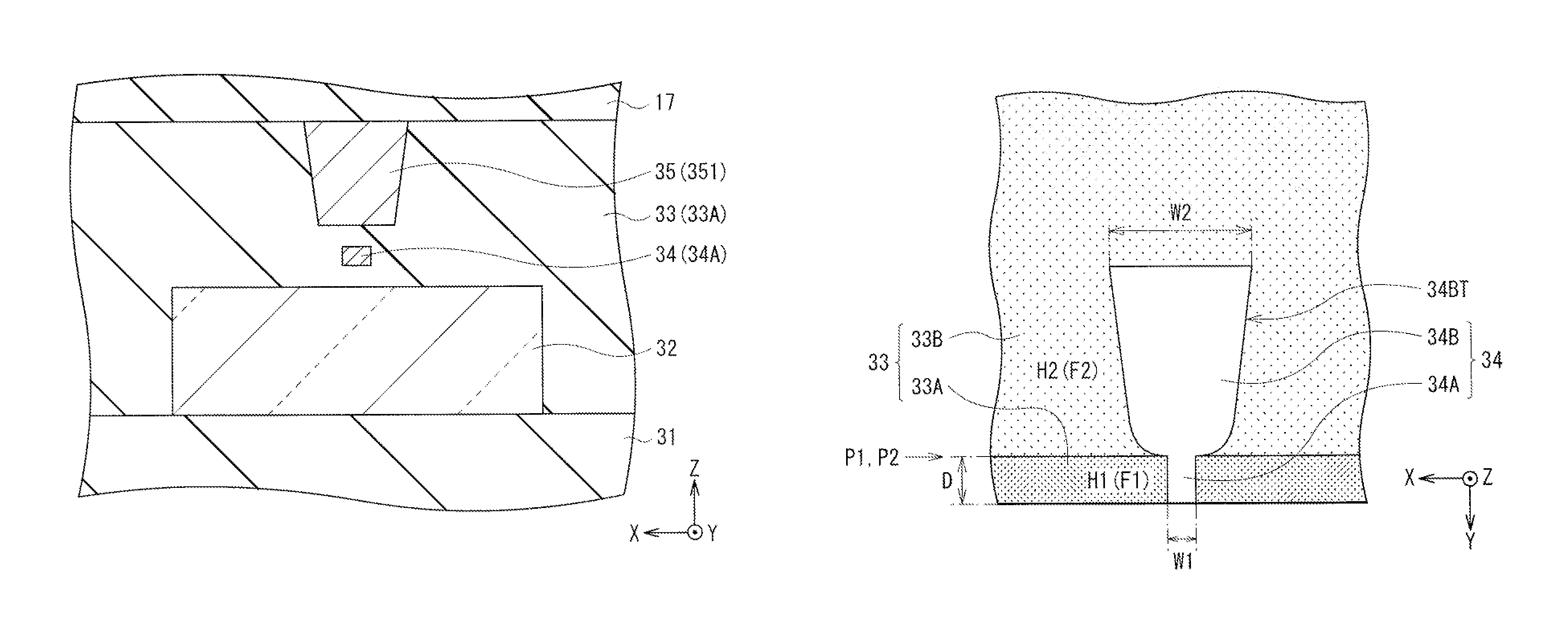
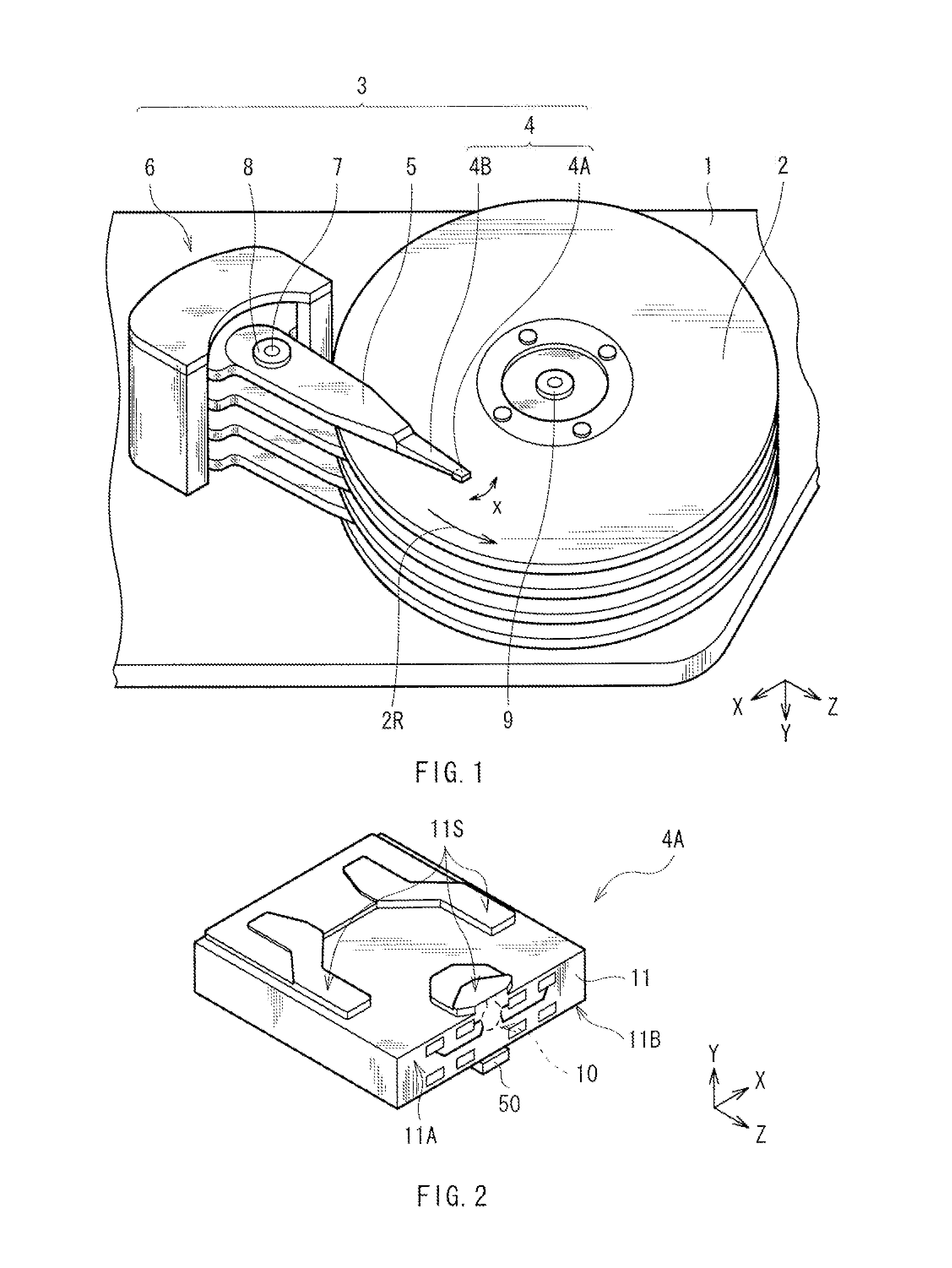
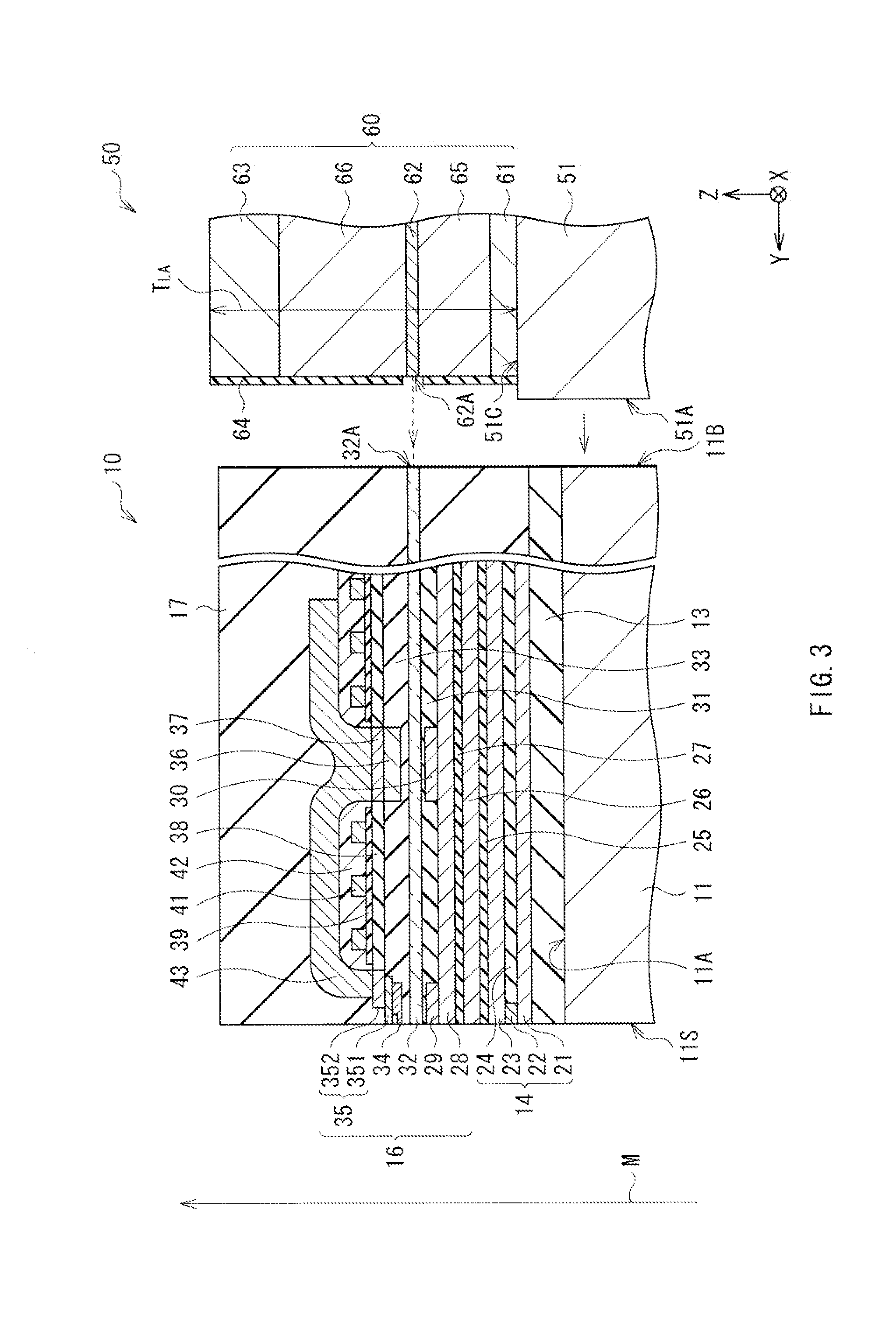
[0027]First, referring to FIG. 1 and FIG. 2, a configuration of a magnetic recording unit using a thermally-assisted magnetic recording head according to an embodiment of the invention will be described. FIG. 1 illustrates a perspective configuration of the magnetic recording unit, and FIG. 2 illustrates a perspective configuration of a magnetic head slider 4A illustrated in FIG. 1 in an enlarged manner.

[0028]The magnetic recording unit described here adop...


PUM

PropertyMeasurementUnit
distanceaaaaaaaaaa
thickness TLAaaaaaaaaaa
wavelengthaaaaaaaaaa

Abstract

The thermally-assisted magnetic recording head of the invention includes: a waveguide; a magnetic pole; a cladding layer provided between the waveguide and the magnetic pole; and a plasmon generator embedded in the cladding layer. The cladding layer includes a first cladding section located on a side close to an air-bearing surface and a second cladding section located on a side far from the air-bearing surface, and a thermal expansion coefficient of the first cladding section is larger than a thermal expansion coefficient of the second cladding section.

Description

BACKGROUND OF THE INVENTION[0001]1. Field of the Invention[0002]The invention relates to a thermally-assisted magnetic recording head in which near-field light is applied to a magnetic recording medium to lower a coercivity thereof so as to record information, and to a head gimbal assembly, a head arm assembly, and a magnetic recording unit that each include the thermally-assisted magnetic recording head.[0003]2. Description of Related Art[0004]In the past, a magnetic recording unit such as a Hard Disk Drive (HDD) has been used for recording and reproducing magnetic information (hereinafter, simply referred to as “information”).[0005]The magnetic recording unit typically includes, in the housing thereof, a magnetic recording medium (a magnetic disk) in which information is recorded, and a magnetic read write head that performs write operation and read operation of the information. The magnetic read write head is formed on a surface of a magnetic head slider, and has an air-bearing s...

Claims


Application Information

Patent Timeline
Patent Type & Authority Patents(United States)
IPC IPC(8): G11B5/187G11B7/135G11B11/10
CPCG11B5/187G11B7/135G11B5/314G11B11/10G11B2005/0021G11B5/6088
Inventor TANAKA, KOSUKEAOKI, SUSUMUKAWAMORI, KEITAKAWATO, HIROKI
Owner TDK CORPARATION
Why Eureka
Try Eureka