Magnetic anisotropy adjusted laminated magnetic thin films for magnetic recording

a magnetic thin film and anisotropy adjustment technology, applied in the field of magnetic thin film media, can solve the problems of too large to be written by a practical write head, the field of recording head field is reduced, and the distance from the recording head is increased.

Inactive Publication Date: 2005-09-06
WESTERN DIGITAL TECH INC
View PDF13 Cites 17 Cited by
  • Summary
  • Abstract
  • Description
  • Claims
  • Application Information

AI Technical Summary

Benefits of technology

[0011]One embodiment of the invention is a laminated magnetic recording medium comprising two magnetic layers separated by a nonmagnetic spacer layer with the lower magnetic layer, i.e., the one farther away from the recording head, having a lower magnetic anisotropy than the upper magnetic layer that is closer to the recording head. In alternative embodiments of the invention one or both of the two magnetic layers in the laminated layer stack can be replaced with an antiferromagnetically (AF) coupled (AFC) layer structure that has an AFC-master and an AFC-slave layer separated by a spacer layer selected to antiferromagnetically couple the AFC-master and AFC-slave layers. In embodiments with one or more AFC layer structures the AFC-slave layers are ignored when adjusting the anisotropy according to the invention. For example, in an embodiment that has the lower magnetic layer replaced with an AF-coupled layer structure, the AFC-master magnetic layer is adjusted to have a lower magnetic anisotropy than the upper magnetic layer. Because the recording head field is reduced with increased distance from the head, selection of the magnetic layers according to the invention helps to respectively match the magnetic anisotropy of the relevant magnetic layer with the head field exerted on it. This matching allows the magnetic layers to be written under optimum conditions by the head at the same head write current. Magnetic media made according to the invention show a single sharp peak in the DC erase noise vs. head write current plot which indicates that the magnetic transitions in the non-slave magnetic layers are written (switch) at the same head write current, leading to the improved magnetic recording performance. In comparison, media using the same magnetic material for both the upper and AFC-master magnetic layers shows double peaks in the DC erase noise vs. head write current plot, indicating an unfavorable write condition in which the two magnetic layers are switched at different head write current. The benefits of the invention are that magnetic pulse width (PW50) is reduced, overwrite (OW) is improved and media signal-to-noise ratio (SoNR) is improved. In one embodiment the upper magnetic layer is selected as a high magnetization alloy so that a thinner layer can be used to achieve the same Mrt and further improve overwrite.

Problems solved by technology

At some point, as V decreases, the stored magnetic information will no longer be stable under the storage device's operating conditions.
However, the increase in Ku is limited by the point where the coercivity Hc, which is approximately equal to Ku / Mr, becomes too great to be written by a practical write heads.
A similar approach is to reduce the Mr of the magnetic layer for a fixed layer thickness, but this is also limited by the coercivity that can be written.
However, this approach has been shown to be deleterious to the intrinsic signal-to-noise ratio (SNR) of the magnetic layer.

Method used


Image

  • Magnetic anisotropy adjusted laminated magnetic thin films for magnetic recording
  • Magnetic anisotropy adjusted laminated magnetic thin films for magnetic recording
  • Magnetic anisotropy adjusted laminated magnetic thin films for magnetic recording

Examples


first embodiment

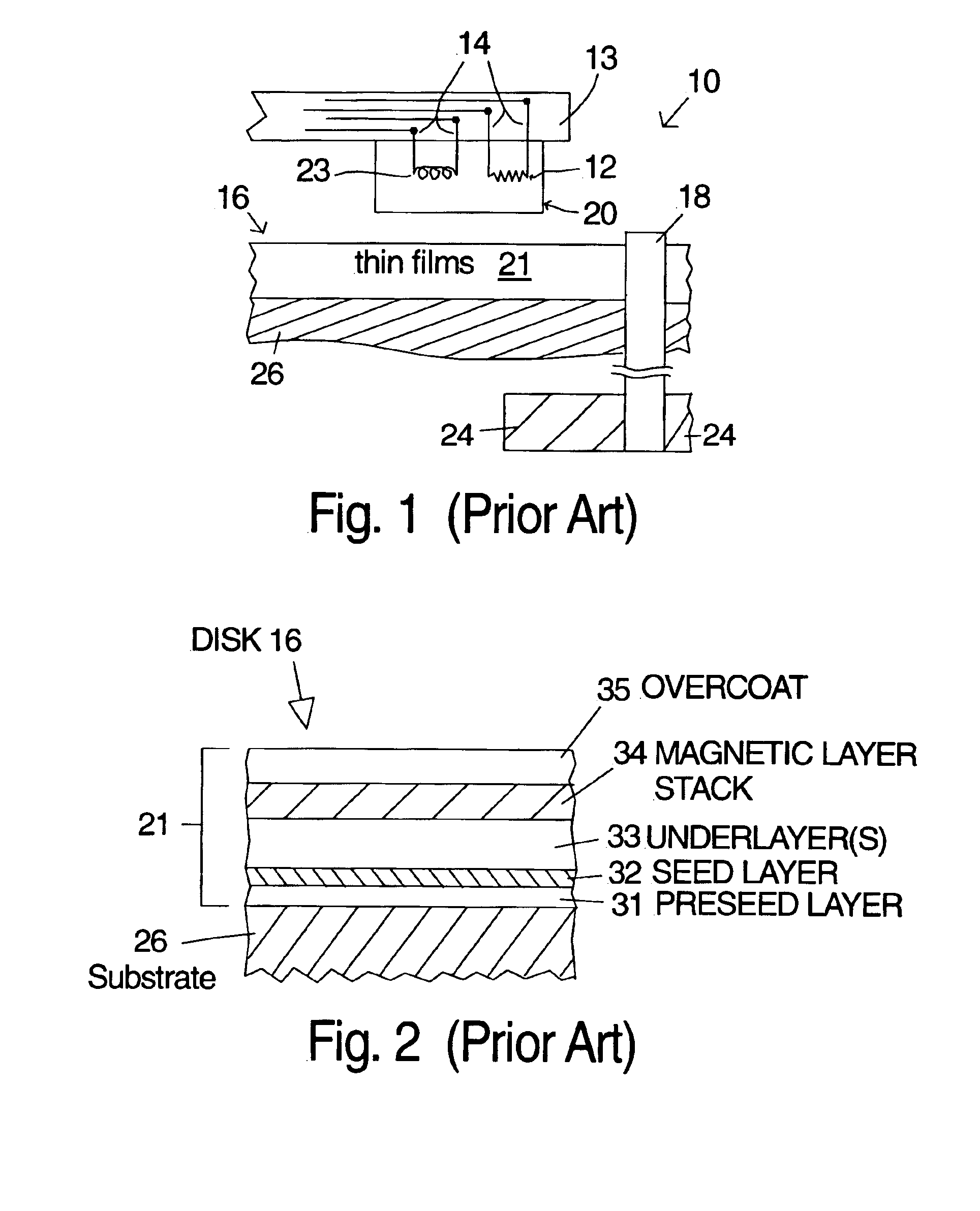
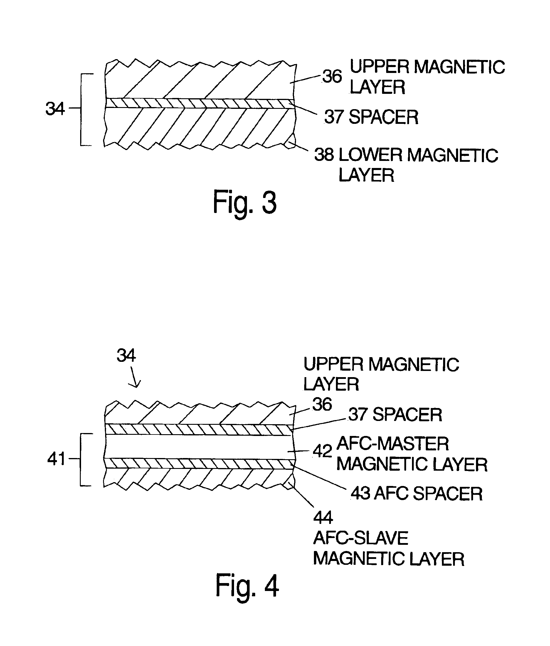
[0019]The layer structure shown in FIG. 2 can be used with a variety of magnetic layer stacks 34. For example, two or more laminated magnetic layers can be used and antiferromagnetically coupled layers structures can be substituted for any or all of the magnetic layers. One embodiment of the magnetic layer stack 34 is composed of a plurality of layers which are further illustrated in FIG. 3. a layer stack 34 according to the invention is a laminated structure including an upper magnetic layer 36 (the magnetic layer nearest to the surface of the disk and, therefore, the head), a spacer layer 37 and a lower magnetic layer 38. The material for the lower magnetic layer 38 is selected to have a lower magnetic anisotropy than the upper magnetic layer 36. The magnetic anisotropy can be adjusted primarily by changing the atomic percentage of platinum in a cobalt based magnetic alloy such as CoPtCr, CoPtCrTa or CoPtCrB. A higher atomic percentage of platinum yields higher magnetic anisotropy...

second embodiment

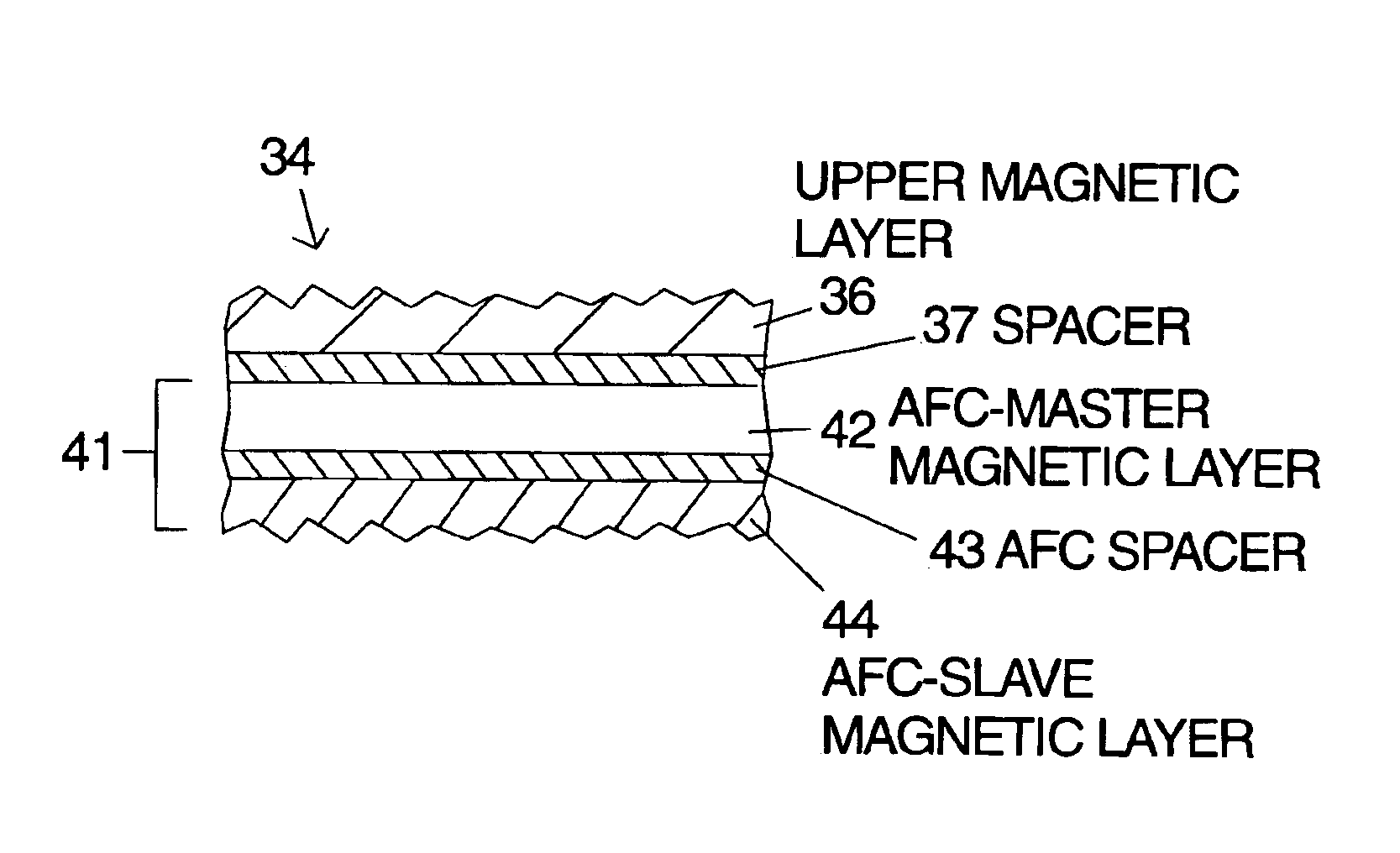
[0020]the layer stack 34 is illustrated in FIG. 4. As noted above an antiferromagnetically coupled layer structure can be substituted for any or all of the magnetic layers in a laminated layer stack. The embodiment in FIG. 4 has an antiferromagnetically coupled layer structure 41 substituted in place of the lower magnetic layer 38 of FIG. 3. An antiferromagnetically coupled layer structure 41 according to the invention has at least three distinct layers with the magnetic layers antiferromagnetically coupled through the nonmagnetic spacer layer. The two magnetic layers of the antiferromagnetically coupled layer structure 41 will be referred to as AFC-master magnetic layer 42 for the upper one and AFC-slave magnetic layer 44 for the lower one. Each of these layers is a ferromagnetic material of the type used in the prior art of thin film disks. Examples of materials suitable include CoCr, CoCrB, CoCrTa, CoPtCr, CoPtCrTa and CoPtCrB. The thickness of the AFC-slave magnetic layer 44 mus...


PUM

PropertyMeasurementUnit
thicknessaaaaaaaaaa
thicknessaaaaaaaaaa
thicknessaaaaaaaaaa

Abstract

Multiple embodiments of the invention are described which include at least two laminated ferromagnetic layers with differing magnetic anisotropy. The independent magnetic layer farther away from the recording head is selected to have a lower magnetic anisotropy to allow magnetic switching of the multiple magnetic layers to occur at approximately the same head write current even though the recording head field is reduced with increased distance from the head. The improved switching yields improved magnetic recording performance. Laminated magnetic media according to the invention can have a single peak in the normalized DC erase noise vs. head write current plot indicating that the magnetic transitions in the non-slave magnetic layers are written at the same head write current. As a result the magnetic pulse width (PW50) is reduced, overwrite (OW) is improved and media signal-to-noise ratio (SoNR) is improved. Alternatively one or both of the laminated ferromagnetic layers can be replaced with an antiferromagnetically (AF) coupled layer structure that has an AFC-master and an AFC-slave layer separated by a spacer layer selected to antiferromagnetically couple the AFC-master and AFC-slave layers.

Description

FIELD OF THE INVENTION[0001]The invention relates to magnetic thin film media with laminated magnetic layers and also to magnetic thin film media with laminated magnetic layers that have one or more antiferromagnetically coupled layer structures included therein and more particularly to magnetic properties and selection of materials used for the plurality of thin films in such media.BACKGROUND OF THE INVENTION[0002]A typical prior art head and disk system 10 is illustrated in block form in FIG. 1. In operation the magnetic transducer 20 is supported by the suspension 13 as it flies above the disk 16. The magnetic transducer 20, usually called a “head” or “slider,” is composed of elements that perform the task of writing magnetic transitions (the write head 23) and reading the magnetic transitions (the read head 12). The electrical signals to and from the read and write heads 12, 23 travel along conductive paths (leads) 14 which are attached to or embedded in the suspension 13. The m...

Claims


Application Information

Patent Timeline
Patent Type & Authority Patents(United States)
IPC IPC(8): G11B5/66G11B5/00G11B5/64G11B5/09G11B5/012G11B5/74G11B5/65G11B5/738G11B5/851
CPCG11B5/66G11B5/012G11B5/09G11B5/656G11B5/74G11B5/851Y10T428/24992G11B2005/0005G11B2005/001Y10T428/1121Y10T428/1193Y10T428/24942G11B2005/0002G11B5/678G11B5/672
Inventor TANG, KAI
Owner WESTERN DIGITAL TECH INC
Why Eureka
Try Eureka