Countertop automatic foam soap dispenser

a soap dispenser and automatic technology, applied in the direction of volume metering, liquid transfer device, instruments, etc., can solve the problems of affecting the service life of the dispenser, so as to achieve the effect of increasing the volume of soap in the soap liquid container and prolonging the service li

Inactive Publication Date: 2014-07-08
ABLEMAN INT
View PDF8 Cites 23 Cited by
  • Summary
  • Abstract
  • Description
  • Claims
  • Application Information

AI Technical Summary

Benefits of technology

[0007]Therefore, Therefore, it is a primary objective of the present invention to overcome the drawbacks of the prior art by providing a countertop automatic foam soap dispenser, not only providing a convenient use, but also improving the service life and practical effect of the automatic foam soap dispenser.
[0011]In addition, the present invention separately installs the automatic foam soap dispenser body and the soap liquid container at the upper and lower position of the countertop of the sink, and the volume of soap contained in the soap liquid container can be increased, and the soap can be refilled as needed. The circuit components and foam soap valve installed inside the automatic foam soap dispenser body have a long service life.

Problems solved by technology

Conventional automatic soap dispensers are generally installed and fixed on walls, and foam soap is usually remained at a soap supplying outlet of the conventional automatic soap dispenser, and the soap liquid will drop directly from the soap supplying outlet after a certain time of using, and thus staining the countertop or the floor.
In addition, the conventional wall-hanging type automatic soap dispenser is installed and fixed on walls, so that the carrying load cannot be over-weight, and the volume of the soap liquid stored in the dispenser body will be limited, and must be refilled frequently.
If the soap liquid is leaked from the dispenser body, the component and the control circuit of the dispenser may be damaged easily, thus incurring higher repair and maintenance costs.

Method used


Image

  • Countertop automatic foam soap dispenser
  • Countertop automatic foam soap dispenser
  • Countertop automatic foam soap dispenser

Examples


Embodiment Construction

[0019]To make it easier for our examiner to understand the technical characteristics, effects and advantages of the present invention, we use preferred embodiments with related drawings for the detailed description of the present invention as follows.

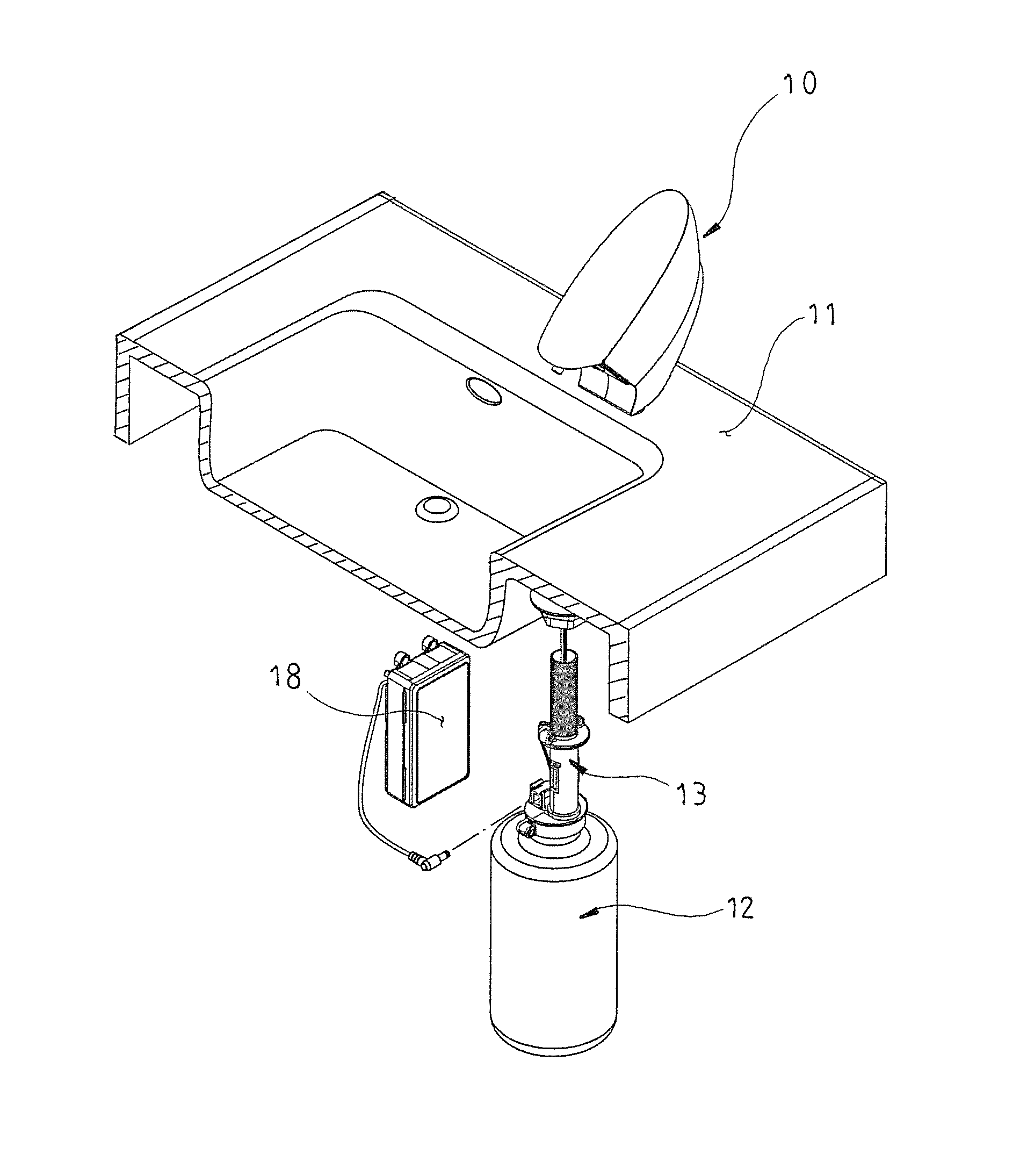
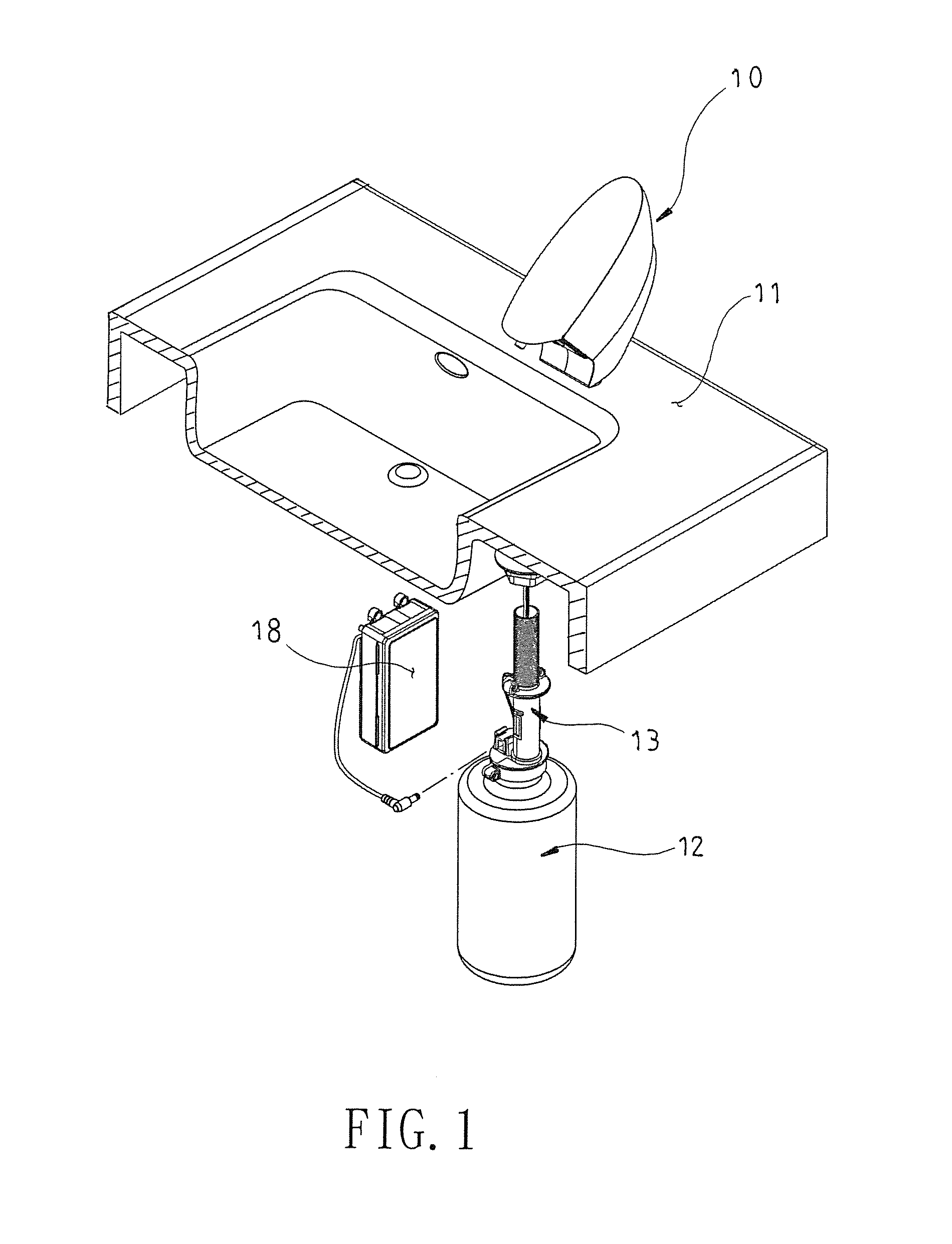
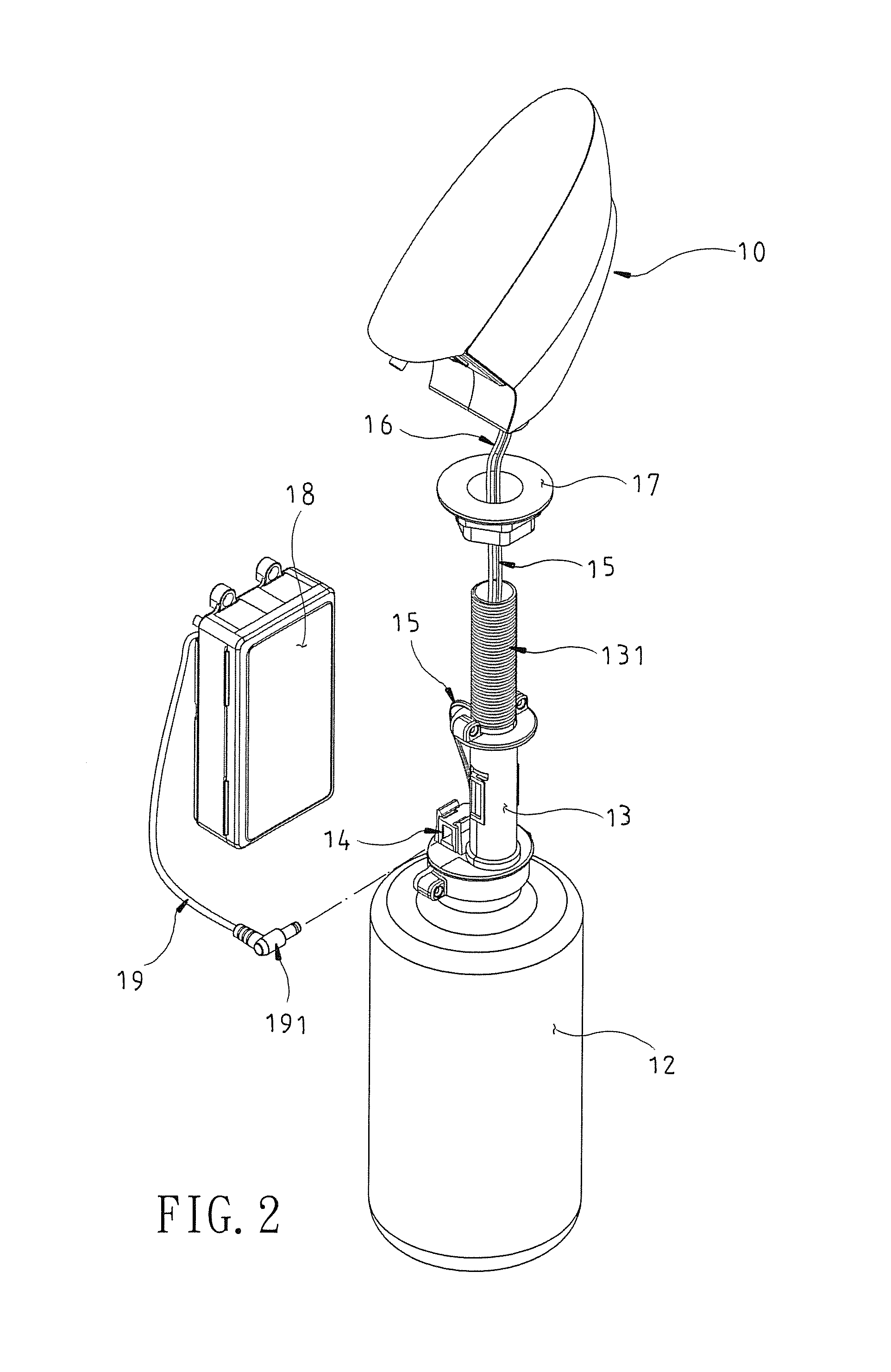
[0020]In FIGS. 1 and 2, a countertop automatic foam soap dispenser of the present invention comprises: an automatic foam soap dispenser body (10), a soap liquid container (12), a circular connecting tube (13) and a battery compartment (18). The soap liquid container (12) is filled with an appropriate quantity of liquid soap and has the circular connecting tube (13) installed at the top of the soap liquid container (12), an external screw thread (131) formed at an upper-half external periphery of the circular connecting tube (13), a connecting socket (14) disposed at the top of the soap liquid container (12) and proximate to a side of the circular connecting tube (13) and electrically coupled to a power cord (15), and the power cord (15)...


PUM


Abstract

A countertop automatic foam soap dispenser includes an automatic foam soap dispenser body, a soap liquid container, a circular connecting tube and a battery compartment. The soap liquid container is filled with an appropriate quantity of liquid soap. The battery compartment supplies electric power to the automatic foam soap dispenser body. The automatic foam soap dispenser body is passed through the circular connecting tube by a soap transmission tube and installed to the bottom inside the soap liquid container. The automatic foam soap dispenser body includes a foam soap valve, a control circuit board, a sensor, a motor controlled by the control circuit board, and a transmission gear set. When a user's hand approaches a sensor of the automatic foam soap dispenser body, the motor drives a cam of the transmission gear set to rotate and compress a foam soap valve to supply the appropriate quantity of foam soap.

Description

BACKGROUND OF THE INVENTION[0001]1. Field of the Invention[0002]The present invention relates to a countertop automatic foam soap dispenser, in particular to the automatic foam soap dispenser installed on a countertop next to a faucet of a sink, and having a soap supplying outlet formed on the automatic foam soap dispenser and aligned towards the sink. The invention provides an automatic sensing foam soap dispenser.[0003]2. Description of the Prior Art[0004]As living standards improve, long-existing manual pressing soap dispensers are gradually replaced by automatic sensing soap dispensers. Conventional automatic soap dispensers are generally installed and fixed on walls, and foam soap is usually remained at a soap supplying outlet of the conventional automatic soap dispenser, and the soap liquid will drop directly from the soap supplying outlet after a certain time of using, and thus staining the countertop or the floor.[0005]In addition, the conventional wall-hanging type automati...

Claims


Application Information

Patent Timeline
Patent Type & Authority Patents(United States)
IPC IPC(8): B67D1/00
CPCA47K5/16A47K5/00A47K2005/1218
Inventor LIN, MOSES-B.
Owner ABLEMAN INT
Why Eureka
Try Eureka