Lubricant composition for chains, and chain

a technology of lubricant composition and chain, which is applied in the direction of driving chains, thickeners, mechanical devices, etc., can solve the problems of short lubrication life of chains, inability to maintain lubrication and abrasion resistance, and inability to hold lubricant in the bushing, etc., and achieve excellent lubricity and abrasion resistance and long lubrication elongation-resistant life

Inactive Publication Date: 2014-07-08
TSUBAKIMOTO CHAIN CO
View PDF36 Cites 11 Cited by
  • Summary
  • Abstract
  • Description
  • Claims
  • Application Information

AI Technical Summary

Benefits of technology

[0015]The present invention has been made with the aim of solving the above problems, and it is an object of the invention to provide a lubricant composition for chains which, when adhered to sliding surfaces, has an appropriate drag force with respect to centrifugal force applied to a chain and fluidity, is prevented from flowing out (being lost), and thereby capable of exhibiting excellent lubricity and abrasion resistance for a long period of time, and to provide the chain.
[0028]According to the second and third aspects of the present invention, when the lubricant composition is present on sliding surfaces, an outflow of the lubricant composition is further reduced and better lubricity and abrasion resistance are exhibited, and therefore the chain has a longer abrasion elongation-resistant life.

Problems solved by technology

In the case of a roll-type bushing, a joining section in rolling up the rectangular base material remains as a seam, and therefore when a chain is constructed by inserting pins into the bushings and uses the lubricant, the lubricant flows out through the seam, resulting in a problem that the chain has a short abrasion elongation-resistant life.
In the case of the bushing of Japanese Patent Application Laid-Open No. 8-277886, however, the lubricant held in the blind grooves tends to flow to the seam because of the influence of centrifugal force applied to the chain, and the lubricant flown out of the blind grooves flows out from the ends in the longitudinal direction of the seam in a short time, resulting in a problem that the lubricant is not held in the bushing for a long period of time, and lubricity and abrasion resistance are not maintained.
With this bushing, although there is no loss of a lubricant caused by the seam, there is a problem that it is impossible to sufficiently prevent leakage of the lubricant from openings at both ends in the axial direction of the bushing.
Hence, there are problems that the lubricant also tends to flow out and the loss of the lubricant is significant.
In the case of the lubricant compositions of Japanese Examined Patent Application Publication No. 63-23239 and Japanese Patent Application Publication Laid-Open No. 9-268298, since ultrahigh molecular weight polyolefin or low molecular weight polyethylene and lubricating grease having a dropping point higher than the melting temperatures of the olefin and polyethylene are mixed and solidified, when such a lubricant composition is used for a chain, there is a problem that the lubricant is not restored and is scattered to the outside and lost by the chain motion, that is, a large motion like swaying, and abrasion would be increased by the time the sliding heat reaches the temperature at which the lubricant melts.

Method used


Image

  • Lubricant composition for chains, and chain
  • Lubricant composition for chains, and chain
  • Lubricant composition for chains, and chain

Examples


embodiment

[0046]The following will explain specifically examples of the present invention and comparative examples, but the present invention is not limited to these examples.

example 1

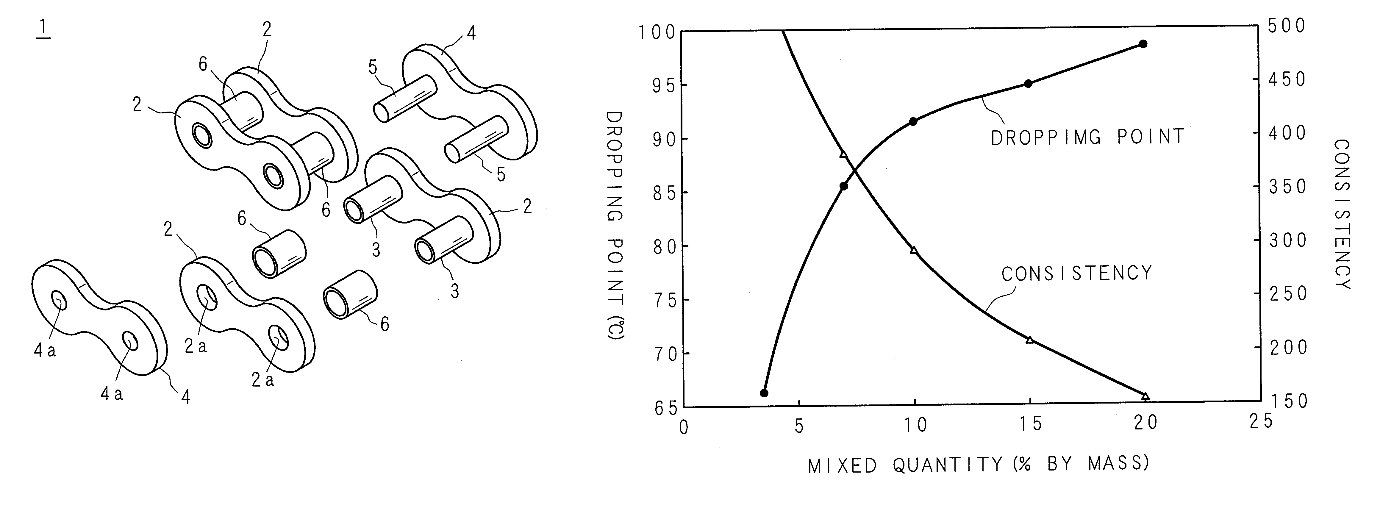
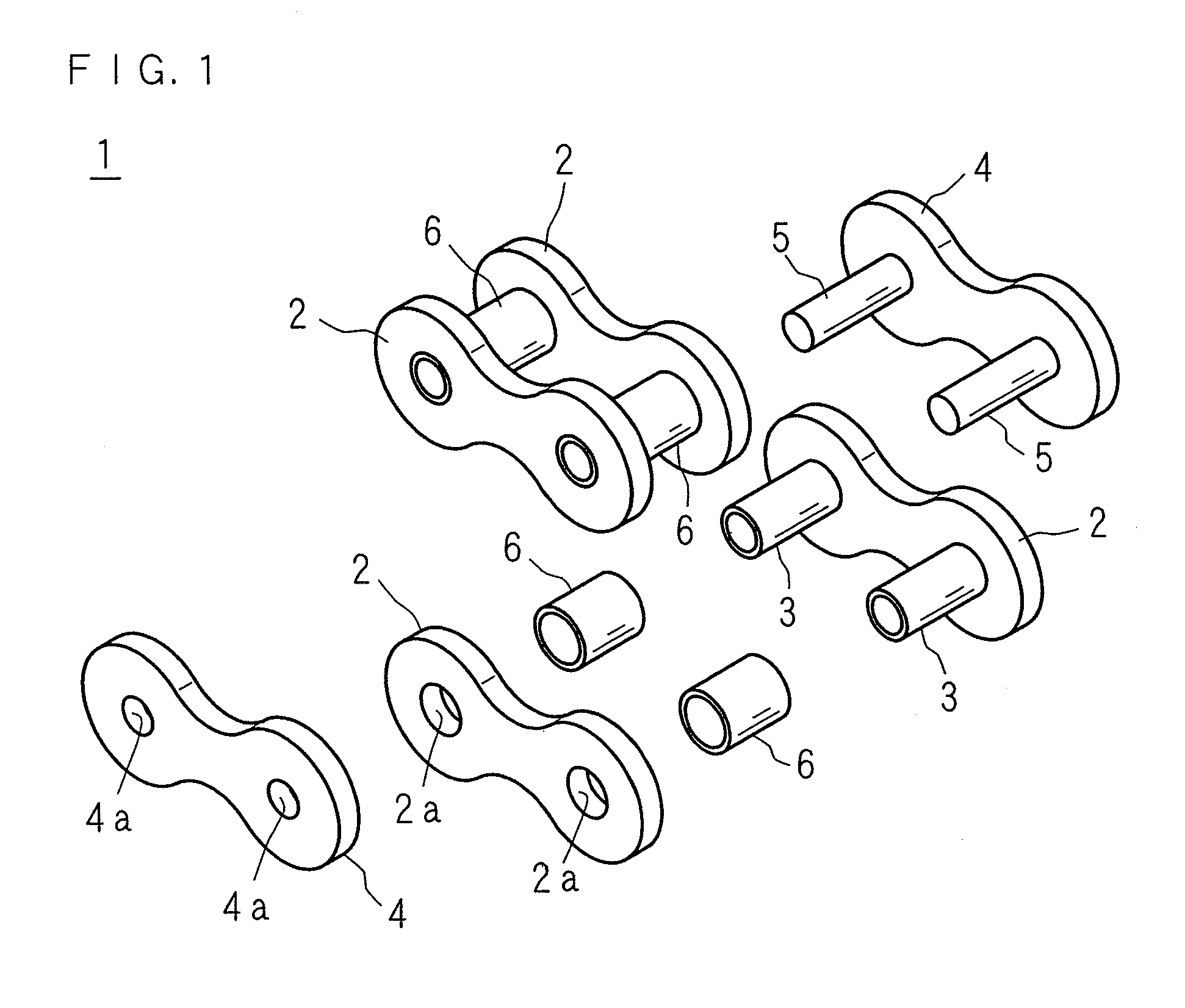
[0047]FIG. 1 is a partial perspective view of a roller-chain-type chain 1 according to Example 1 of the present invention.

[0048]Each of inner link plates 2 and outer link plates 4 of the chain 1 has the shape of substantially an eight and is fabricated by forming an arc-shaped dent inwardly in the center of both side edges of a flat plate member in the shape of an ellipse and opening holes 2a, 2a or holes 4a, 4a near both poles of the ellipse. The width of the plate and the diameter of the hole are greater in the inner link plate 2 than in the outer link plate 4. The inner link plates 2 are connected together by interference-fitting one ends of cylindrical bushings 3, 3 into the two holes 2a, 2a of one inner link plate 2 and interference-fitting the other ends of the bushings 3, 3 into the holes 2a, 2a of the other inner link plate 2. Cylindrical rollers 6, 6 with an inner diameter larger than the outer diameter of each of the bushings 3, 3 are fitted rotatably on the bushings 3, 3....

example 2

[0053]A chain of Example 2 was produced in the same manner as in Example 1 except that 15% by mass of “Mitsui Hi-WAX 320P” (polyethylene wax having an average molecular weight of 3000 and a melting point of 109° C. (DSC method): manufactured by Mitsui Chemicals Inc.) was mixed as the wax contained in the lubricant composition.


PUM

PropertyMeasurementUnit
temperatureaaaaaaaaaa
sliding speedaaaaaaaaaa
surface pressureaaaaaaaaaa

Abstract

A chain is constructed by alternately connecting a pair of outer link plates connected together with pins and a pair of inner link plates connected together with bushings into which adjacent pins of adjacent pairs of outer link plates are inserted. On the outer and inner surfaces of component parts of the chain, a lubricant composition for chains containing 95% to 80% by mass of a lubricant which is liquid at room temperature and 5% to 20% by mass of a wax which is solid at room temperature and having a consistency of from 60 to 475 and a dropping point of from 60° C. to 120° C., is adhered.

Description

[0001]This application is the national phase under 35 U.S.C. §371 of PCT International Application No. PCT / JP2008 / 067001 which has an International filing date of Sep. 19, 2008 and designated the United States of America.BACKGROUND[0002]1. Technical Field[0003]The present invention relates to a lubricant composition for chains and to a chain having the lubricant composition for chains adhered to its surface.[0004]2. Description of Related Art[0005]As a power transmission mechanism and a conveyer mechanism, chains such as bushing chains and roller chains are conventionally used. A bushing chain is constructed by alternately connecting a pair of outer link plates, which are connected together with two pins at both ends, and a pair of inner link plates having two bushings at both ends so that the pins on the adjoining sides of two pairs of outer link plates are fitted into the bushings. A roller chain additionally includes rollers fitted on the bushings.[0006]The bushing has a cylindri...

Claims


Application Information

Patent Timeline
Patent Type & Authority Patents(United States)
IPC IPC(8): F16G13/02C10M159/06C10M173/00F16N7/16
CPCF16G13/06C10M119/02C10M159/06C10M169/02C10M2203/1006C10M2205/14C10M2205/146C10M2205/16C10M2205/166C10N2230/06C10N2250/10C10N2030/06C10N2050/10
Inventor TANAKA, KOJI
Owner TSUBAKIMOTO CHAIN CO
Why Eureka
Try Eureka