Preparative liquid chromatograph system

a liquid chromatograph and liquid chromatograph technology, applied in the field of preparation liquid chromatograph systems, can solve the problems of high difficulty in obtaining the delay volume with high accuracy, affecting and problematically difficult to accurately separate the component corresponding to the desired peak, so as to save system costs and achieve accurate delay time occurring, the effect of improving the accuracy of preparative separation of the desired componen

Active Publication Date: 2014-07-08
SHIMADZU CORP
View PDF10 Cites 2 Cited by
  • Summary
  • Abstract
  • Description
  • Claims
  • Application Information

AI Technical Summary

Benefits of technology

[0022]As compared with conventional products, the preparative liquid chromatograph system according to the present invention can more accurately obtain delay time occurring in the period from detection of a component in an eluate with a detector to preparative separation with a fraction collector, or delay volume which expresses the delay time by volumes of the channel route. It is thus possible to improve the accuracy in preparative separation of the desired component. Moreover, it is also possible to obtain the delay data solely by utilizing a detector which is used for normal preparative separation or LC analysis. Accordingly, since addition of another detector is not necessary, cost for the system can be saved.
[0023]If the preparative liquid chromatograph system according to the present invention is provided with a sample introduction means (auto sampler) for automatically selecting each portion of the eluate separated in the plurality of containers and for sequentially subjecting the selected portion of the eluate to an LC analysis, a series of operations for calculating the delay data can be almost fully automated without any manual operation.

Problems solved by technology

However, since such estimation sometimes includes errors, it is difficult to obtain the delay volume with high accuracy.
Furthermore, an erroneous delay volume may be set due to human errors such as miscalculation by the user.
Accordingly, it has been problematically difficult to accurately separate the component corresponding to a desired peak that appears in a chromatogram.
However, this method does not consider inner volumes of portions which are not included in the flow channel between the two detectors, such as channel-changing valves and dispenser nozzles, and thus problematically the calculated delay volume may not be sufficiently accurate.
Further, disposing two detectors respectively on both the upstream and downstream sides of the fraction collector poses a problem of a complex structure.
However, similarly with the foregoing prior art, this method does not consider the volumes of a flow changing valve and a dispenser nozzle inside the fraction collector.
Further, addition of another detector only for measuring the delay time leads to an increase in the production cost.[Patent Document 1] U.S. Pat. No. 7,086,279[Patent Document 2] U.S. Pat. No. 6,767,467

Method used


Image

  • Preparative liquid chromatograph system
  • Preparative liquid chromatograph system
  • Preparative liquid chromatograph system

Examples


Embodiment Construction

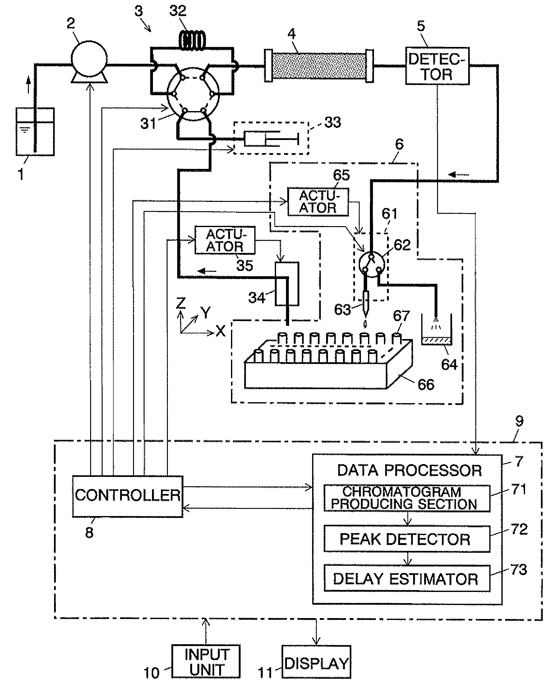
[0053]The following description will discuss a preparative liquid chromatograph system (hereinafter, referred to as a preparative LC system) according to one embodiment of the present invention with reference to the attached figures. FIG. 1 is a configuration diagram showing the main parts of the preparative LC system according to the present embodiment.

[0054]In the preparative LC system, a liquid feed pump 2 suctions a mobile phase stored in a mobile phase container 1 and supplies it through an injector unit 3 into a column 4 at a constant flow rate. The injector unit 3 includes a 6-port, 2-position (flow channels indicated by solid lines and flow channels indicated by dotted lines shown in FIG. 1) high pressure valve 31, a sample loop 32, a measuring unit 33 having a measuring syringe, a sampler 34, an actuator 35 which moves the sampler 34 in three axis directions of X, Y and Z shown in FIG. 1, and other members. The injector unit 3 injects a predetermined amount of a sample liqu...


PUM

PropertyMeasurementUnit
preparative liquid chromatographaaaaaaaaaa
timeaaaaaaaaaa
liquid chromatographaaaaaaaaaa

Abstract

A sample is introduced from an injector unit into a mobile phase. One target component is separated into a plurality of vials by a fraction collector. Next, a sampler sequentially suctions the eluate from the plurality of the vials and performs an LC analysis on each of the eluate portions, thereby producing a chromatogram. A peak detector calculates the peak area corresponding to the amount of the target component in each chromatogram. A delay estimator extracts the peak area in the fraction having the maximum peak area and the peak areas in the previous and succeeding fractions on the time axis of the foregoing fraction. Then, the delay estimator estimates a delay volume from a detector to the tip end of the dispenser nozzle based on data such as the peak areas, the flow rate of the liquid fed from the pump, positions of the vials, and the position of the peak of the target component in the chromatogram detected by the detector, and stores the delay volume. Upon preparative separation of a desired component, a delay time is calculated based on the delay volume and the flow rate and the timing for the preparative separation is controlled based on the delay time.

Description

CROSS-REFERENCE TO THE RELATED APPLICATIONS[0001]This application is a national stage of international application No. PCT / JP2008 / 002231, filed on Aug. 19, 2008, the entire contents of which are incorporated herein by reference.TECHNICAL FIELD[0002]The present invention relates to a preparative liquid chromatograph system which fractionates an eluate containing a component isolated in a column, and collects the eluate separately in a plurality of containers.BACKGROUND ART[0003]Preparative liquid chromatograph systems (hereinafter referred to as a preparative LC system) have been known as systems which fractionate and collect a plurality of components contained in a liquid sample by use of a high-performance liquid chromatography (HPLC). A preparative LC system detects a sample component in an eluate when the eluate passes through a detector such as an ultraviolet-visible light absorption detector and controls preparative separation of the eluate in a fraction collector at a timing b...

Claims


Application Information

Patent Timeline
Patent Type & Authority Patents(United States)
IPC IPC(8): G06F19/00G01N30/06
CPCG01N30/82G01N30/8665G01N30/88
Inventor MARUYAMA, SHUZO
Owner SHIMADZU CORP
Why Eureka
Try Eureka