Cleaner head for a vacuum cleaner

a vacuum cleaner and cleaner head technology, applied in the field of vacuum cleaners, to achieve the effect of reducing vibration and taking up assembly tolerances

Active Publication Date: 2014-07-15
DYSON TECH LTD
View PDF19 Cites 63 Cited by
  • Summary
  • Abstract
  • Description
  • Claims
  • Application Information

AI Technical Summary

Benefits of technology

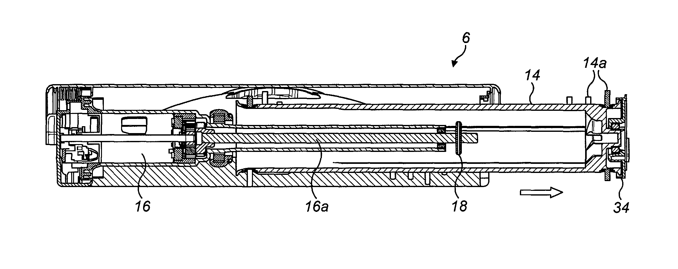
[0008]The brush bar is straightforwardly and conveniently removed by sliding the brush bar out through an opening at the opposite end of the cleaner head to the drive assembly end. There is no need to provide any complicated hinging mechanisms to allow for removal of the brush bar. Instead, the drive assembly can be fixedly mounted in the cleaner head.
[0009]In use, the bearing helps maintain a stable clearance between the brush-bar and the drive assembly. Nevertheless, because the brush-bar engages the bearing in an axial-sliding fit, straightforward axial sliding removal of the brush bar is not inhibited by this bearing.
[0011]The bearing may be soft-mounted on the drive-assembly. For example, a resilient member—such as an elastomeric mounting collar or ring—may be provided between the inner race and the drive assembly. Similarly, the brush bar may be soft-mounted on the bearing. For example, a resilient member—such as an elastomeric mounting collar or ring—may be provided between the bearing outer race and the brush bar. Preferably, a resilient member is provided between both the inner race and the drive assembly, and the outer race and the brush bar. This helps reduce vibrations transmitted to the brush bar through the drive assembly.
[0012]The drive assembly may engage the brush bar via a drive dog. This drive dog may also engage the brush-bar in a corresponding axial-fit so as not to inhibit removal of the brush-bar through the opening in the opposite end of the cleaner head. In this sort of arrangement, the use of a soft-mounted bearing is particularly advantageous in taking up assembly tolerances, particularly if the drive-dog is spaced at the opposite end of the cleaner head from the drive assembly. Spacing the drive-dog and bearing towards opposite ends of the cleaner head in this manner provides a stable support for the brush bar.

Problems solved by technology

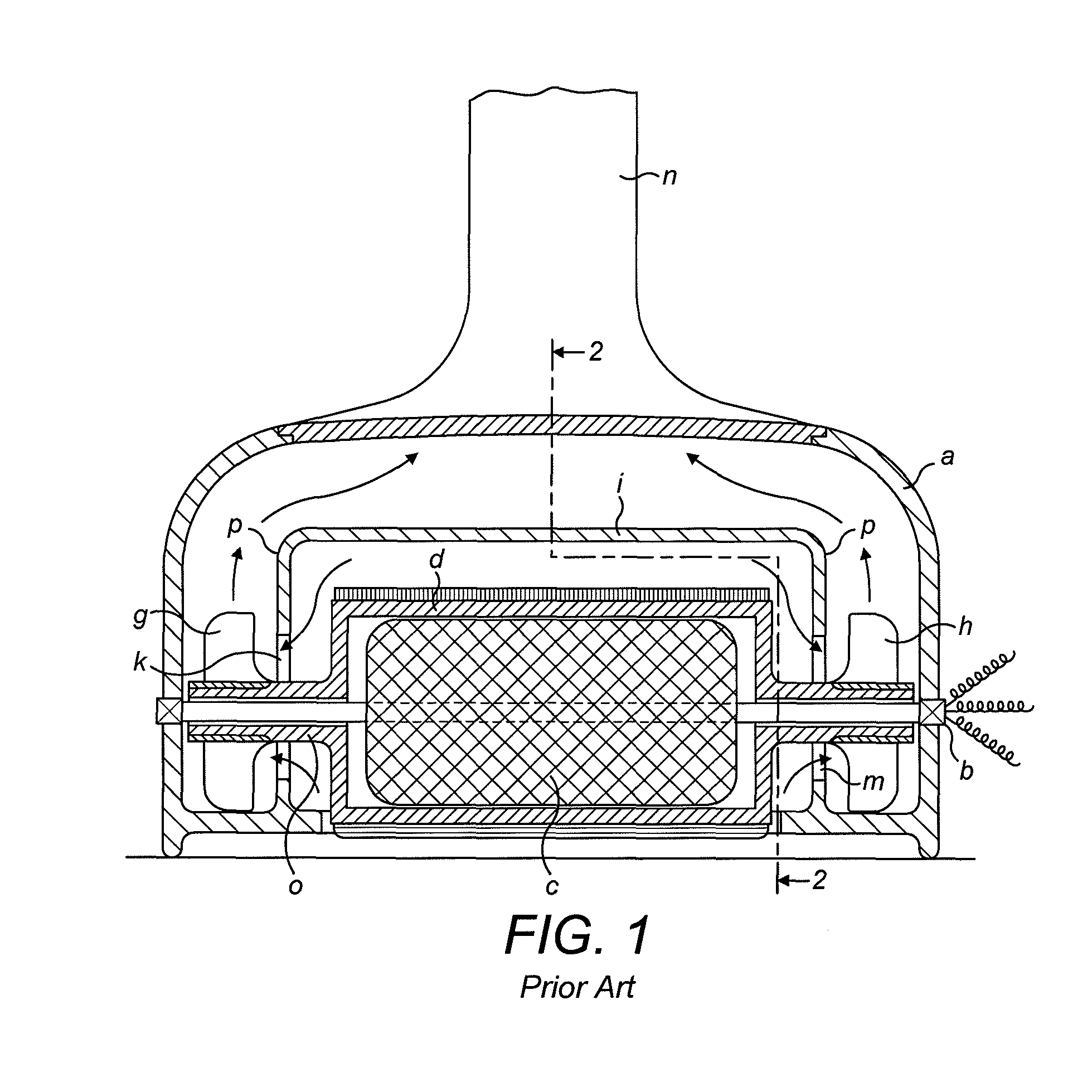
However, in the arrangement in U.S. Pat. No. 1,914,834 this is made impossible because the armature c prevents separate removal of the brush bar d.

Method used


Image

  • Cleaner head for a vacuum cleaner
  • Cleaner head for a vacuum cleaner
  • Cleaner head for a vacuum cleaner

Examples


Embodiment Construction

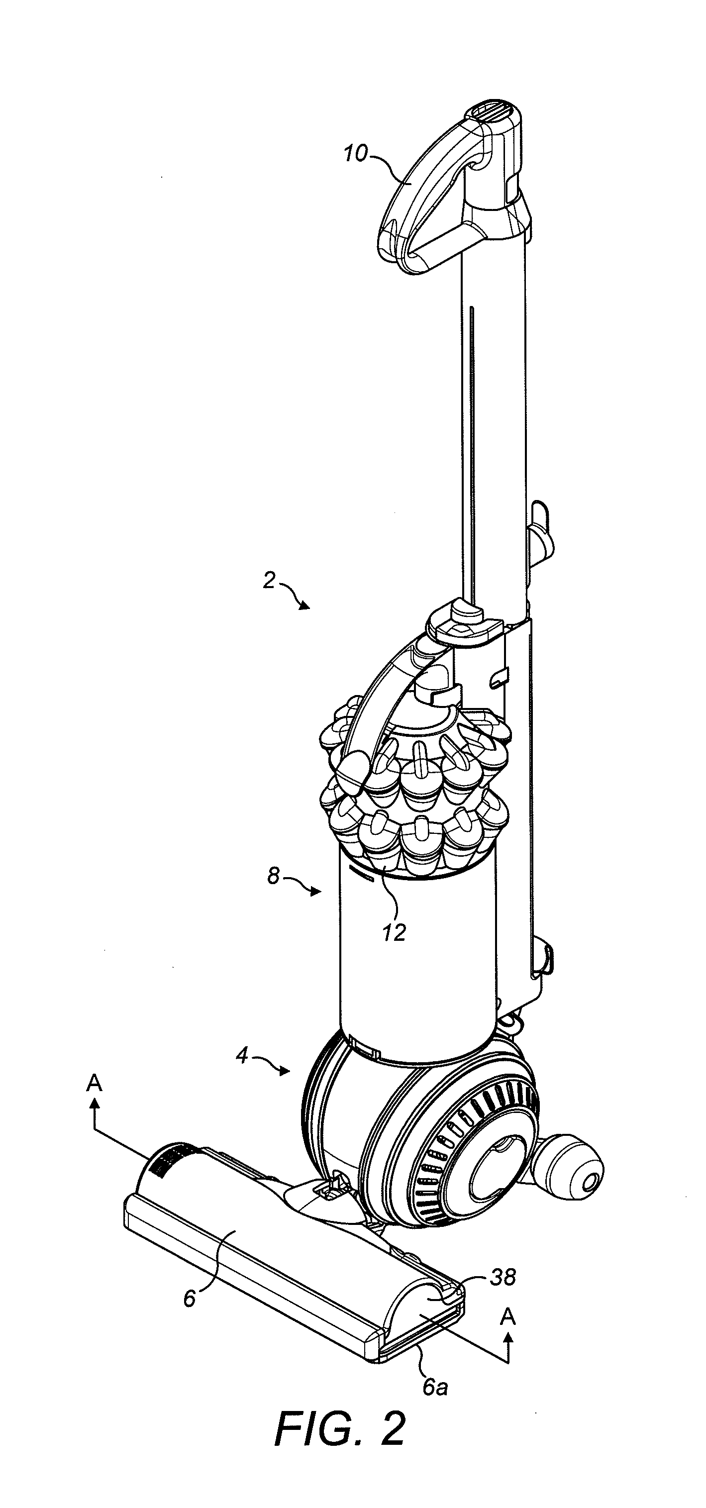
[0023]FIG. 2 shows an upright vacuum cleaner 2. The cleaner 2 has a rolling head assembly 4 which carries a fixed cleaner head 6, and an ‘upright’ body 8 which can be reclined relative to the head assembly 4 and which includes a handle 10 for manouevring the cleaner 2 across the floor. In use, a user grasps the handle 10 and reclines the upright body 8 until the handle 10 is disposed at a convenient height for the user; the user can then roll the vacuum cleaner 2 across the floor using the handle 10 in order to pick up dust and other debris on the floor. The dust and debris is drawn in through a downward-facing suction opening—which opening is provided in a soleplate 6a on the underside of the cleaner head 6—by a motor-driven fan housed on-board the cleaner 2. From here, the dirt-laden air stream is ducted in conventional manner under the fan-generated suction pressure to a cyclonic separating apparatus 12, where dirt is separated from the air before the relatively clean air is then...


PUM


Abstract

A cleaner head for a vacuum cleaner houses a hollow brush bar mounted for rotation about an axis. This brush bar is driven by a motor housed inside the hollow brush bar, the motor forming part of a drive assembly supported at one end of the cleaner head. The brush bar is arranged for removal from the cleaner head by sliding the brush bar along the axis and out through an opening at the opposite end of the cleaner head and the brush bar is rotatably supported in clearance around the drive assembly by a first bearing, which bearing engages the brush bar in a corresponding axial-sliding fit to allow said sliding removal of the brush bar.

Description

REFERENCE TO RELATED APPLICATIONS[0001]This application claims the priority of United Kingdom Application No. 1200348.9, filed Jan. 10, 2012, the entire contents of which are incorporated herein by reference.FIELD OF THE INVENTION[0002]The present invention relates to the field of vacuum cleaners, and in particular to a cleaner head for a vacuum cleaner.BACKGROUND OF THE INVENTION[0003]The invention is concerned specifically with cleaner heads which incorporate a motor-driven agitator. The vacuum cleaner, on the other hand, may be of any general type. For example, the cleaner head may be a fixed cleaner head on an upright vacuum cleaner, or alternatively it may be the cleaner head of a floor tool used with a cylinder vacuum cleaner or stick-vac cleaner.[0004]It is conventional to provide the cleaner head of a vacuum cleaner with an agitator, such as a rotating brush bar, for agitating or “beating” a floor surface—particularly carpet—to improve pick-up performance.[0005]Although the ...

Claims


Application Information

Patent Timeline
Patent Type & Authority Patents(United States)
IPC IPC(8): A47L9/04
CPCA47L9/04A47L9/0411A47L9/0438A47L9/0477A47L9/0405A47L9/0466A47L9/0455A47L9/00
Inventor GENN, STUART LLOYDLESNIOWSKI, CHRISTOPHERCOURTNEY, STEPHEN BENJAMIN
Owner DYSON TECH LTD
Why Eureka
Try Eureka