Fuel tank opening and closing device

a technology of opening and closing device and fuel tank, which is applied in the direction of wing accessories, liquid handling, packaging goods types, etc., can solve the problems of increasing the precision of through hole forming, and requiring a great deal of effort, and achieve the effect of stable attitud

Active Publication Date: 2014-07-15
TOYODA GOSEI CO LTD
View PDF12 Cites 6 Cited by
  • Summary
  • Abstract
  • Description
  • Claims
  • Application Information

AI Technical Summary

Benefits of technology

[0007]An advantage of some aspects of the invention is to provide a fuel tank opening and closing device that is able to open and close in a stable attitude without needing to increase the forming precision of the bearing mechanism that supports the opening and closing member so as to be rotatable.
[0010]Also, the opening and closing member is supported so as to be rotatable by having the shaft inserted in the shaft support recess of the bearing mechanism provided on the tank opening forming member. At the inner wall of the shaft support recess, a plurality of shaft restriction projections having a cross section arc shaped shaft support surface are provided, these contact part of the shaft outer periphery and are supported to be rotatable. The plurality of shaft restriction projections are divided with a groove between them, so compared to a case of supporting the shaft by forming the cross section circle shape simply by the shaft support recess, do not require high forming precision of the shaft support surface of each shaft bearing projection, and forming work is easier. In fact, when forming the tank opening forming member using resin, even if each shaft restriction projection has slight deformation of the circle shape formed by their arcs due to shrinkage of the resin, this is supported along part of the outer periphery of the shaft of the opening and closing member so that shaft shaft core displacement does not occur, so there is no unevenness or decrease in the seal surface pressure of the opening and closing member that comes with shaft positional displacement.
[0012]With application example 3, the shaft support recess is equipped with an opening that opens in an opposite direction to an insertion direction of the fueling nozzle, the shaft restriction projection includes an opening projection projecting so as to restrict an opening width of the shaft support recess more narrow than an diameter of the shaft, and the opening projection elastically deforms and holds the shaft at a position touching the shaft restriction projection when the shaft is inserted in the shaft support recess, thereby preventing the shaft from slipping off the shaft support recess. With this constitution, the opening projections can further prevent shaft positional displacement.
[0013]With application example 4, it is possible to use a constitution for which the he tank opening forming member comprises a connecting tube which forms the fuel path, an inlet forming member having the inlet mounted inside that connecting tube, and a fitting member attached to the inlet forming member and forming the support recess, and the inlet forming member includes a restraining member that is inserted in the opening of the shaft support recess and retains the shaft. With this constitution, the shaft support recess can easily have the shaft inserted from the opening, and furthermore, it is possible for the restraining member to prevent falling out of the shaft when the fitting member and the inlet forming member are linked.

Problems solved by technology

Because of this, there was the problem that a great deal of effort was required to increase the through hole forming precision.

Method used


Image

  • Fuel tank opening and closing device
  • Fuel tank opening and closing device
  • Fuel tank opening and closing device

Examples


Embodiment Construction

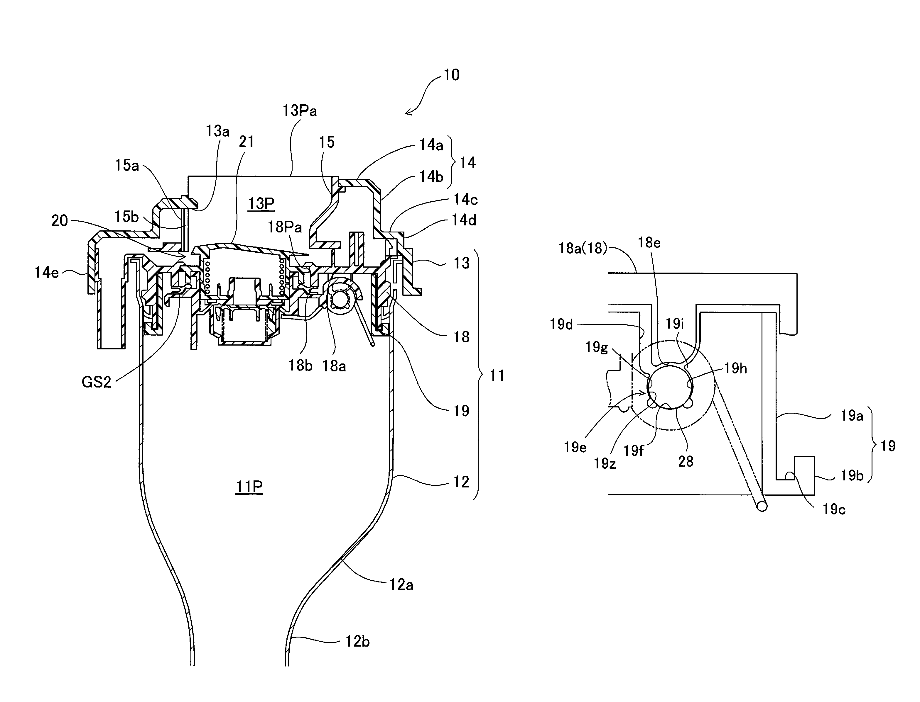
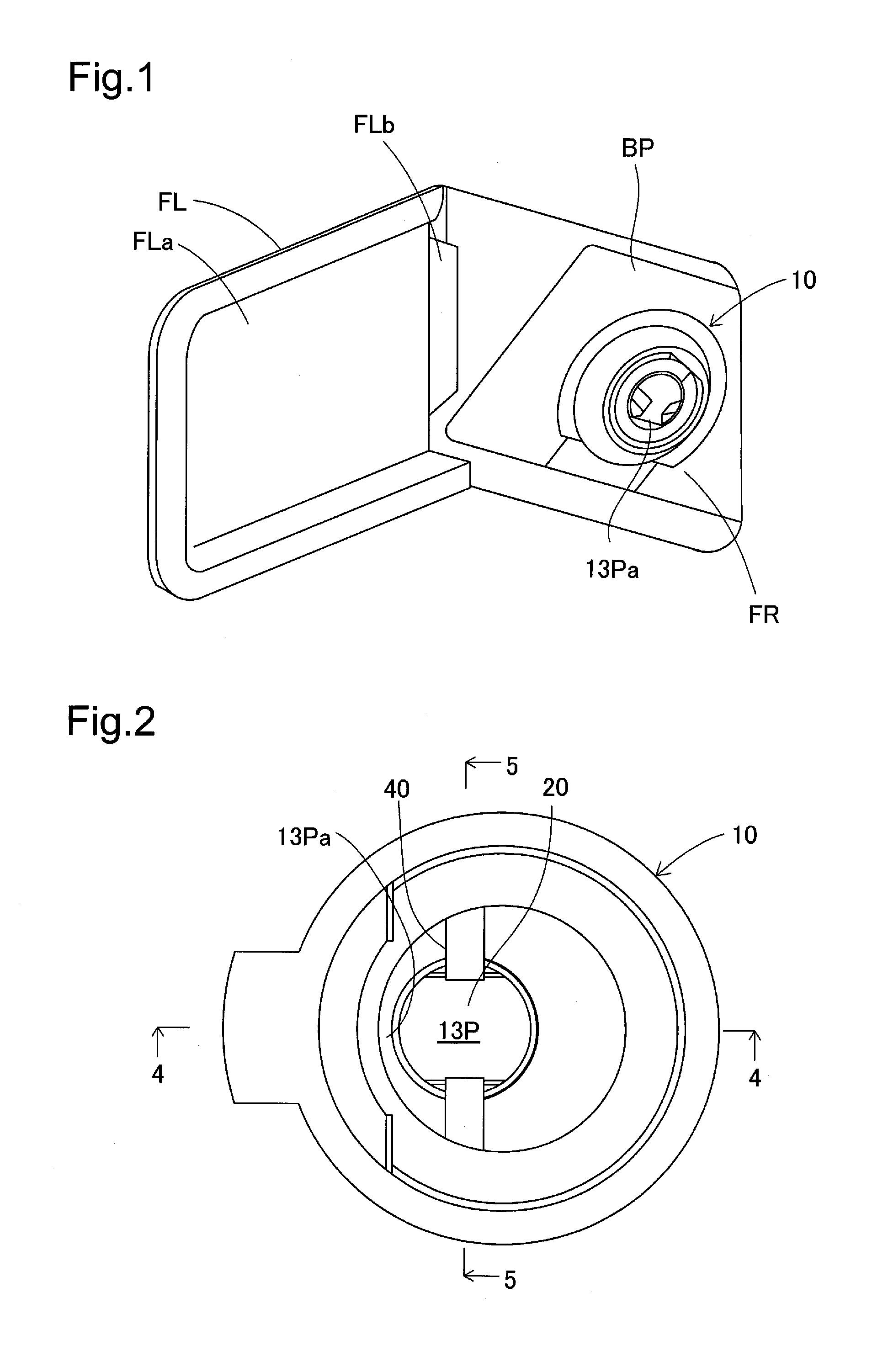
[0037](1) General Constitution of the Fuel Tank Opening and Closing Device

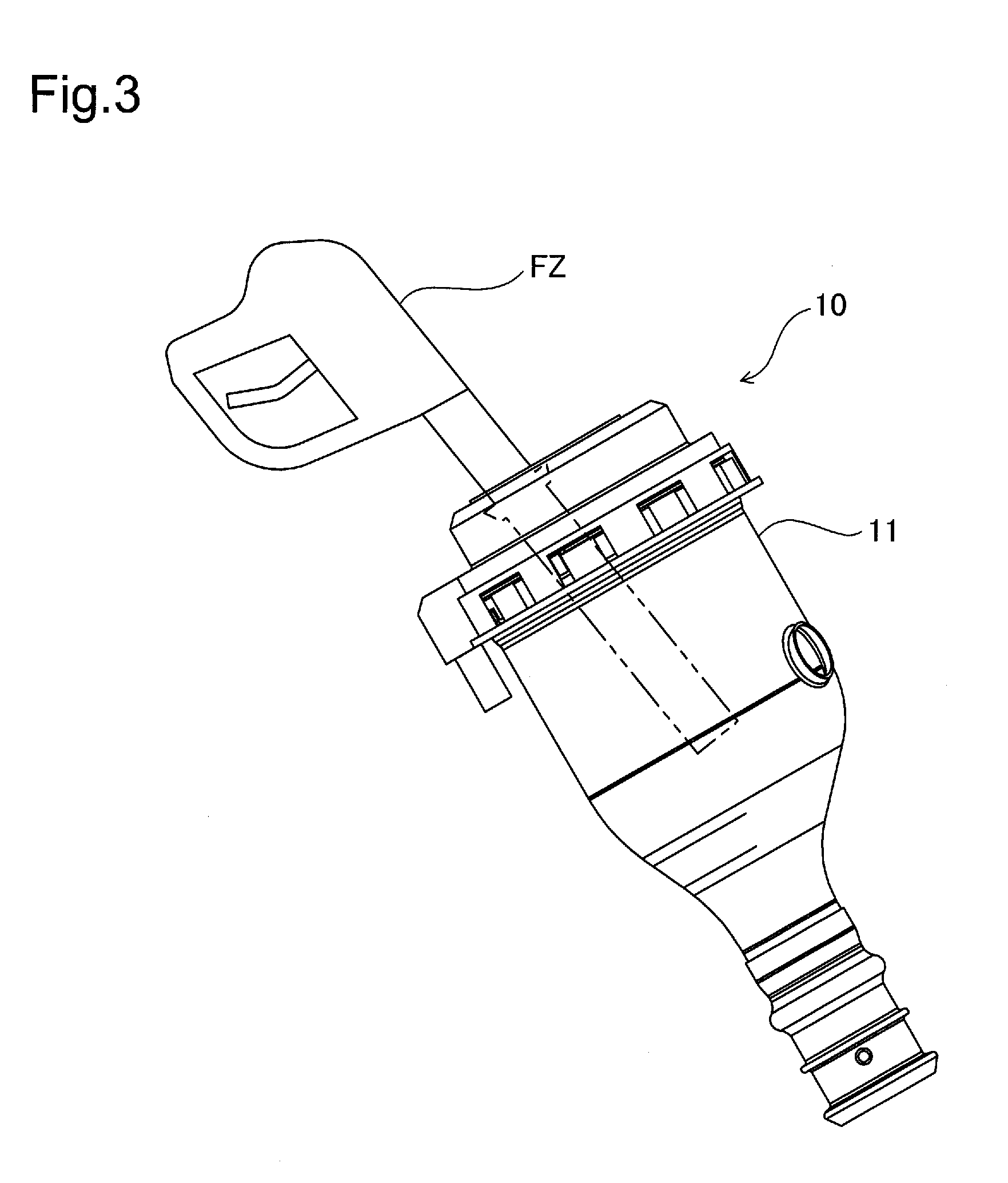
[0038]FIG. 1 shows the back part of a vehicle using the fuel tank opening and closing device of an embodiment of the present invention. At the back part of the car body of the vehicle, a fueling lid FL for fueling fuel (light oil) is supported to be able to open and close. The fueling lid FL is supported so that the lid main body FLa following the outer panel of the car body is able to open and close at the outer panel of the car body via the hinge FLb. The space that opens for the fueling lid FL becomes the fueling chamber FR, and inside this fueling chamber FR is placed the fueling tank opening and closing device 10 supported on a base plate BP. The fuel tank opening and closing device 10 is a mechanism for supplying fuel to the fuel tank without using a fuel cap, and it is a mechanism that, after the fueling lid FL is opened, supplies fuel to the fuel tank from the fueling nozzle by opening the fuel path wi...


PUM

PropertyMeasurementUnit
timeaaaaaaaaaa
inner diameter D0aaaaaaaaaa
diameteraaaaaaaaaa

Abstract

A fuel tank opening and closing device is equipped with a flap valve mechanism arranged inside the tank opening forming member, having an opening and closing member for which the inlet is opened and closed by being pressed by the tip of the fueling nozzle, a shaft provided at the tip of the opening and closing member, and a bearing mechanism provided on the tank opening forming member for supporting the shaft so as to be rotatable. The bearing mechanism has a shaft support recess in which the shaft is inserted and a plurality of shaft restriction projections provided projecting from the wall surface of the shaft support recess, and the shaft restricting projections have a cross section arc shaped shaft support surface such that there is contact with a portion of the outer periphery of the shaft.

Description

[0001]This application claims the benefit of and priority from Japanese Application No. 2010-148759 filed Jun. 30, 2010, the content of which is incorporated herein by reference.BACKGROUND OF THE INVENTION[0002]1. Field of the Invention[0003]The present invention relates to a fuel tank opening and closing device for opening a flap valve using the insertion force of a fueling nozzle to fuel a fuel tank.[0004]2. Description of the Related Art[0005]An example of a fuel tank opening and closing device is disclosed in JP-A 2007-331518 as a fuel cap including a flap valve mechanism. The flap valve mechanism is equipped with an opening and closing member arranged at the inlet of the fuel path, and the shaft protruding from the end part of the opening and closing member, the shaft is inserted into the through hole of the tank opening forming member and supported to be rotatable. The opening and closing member is sealed by energization of the spring in the closing direction. With this consti...

Claims


Application Information

Patent Timeline
Patent Type & Authority Patents(United States)
IPC IPC(8): B65B3/04B60K15/04
CPCB60K15/04B60K15/0406B60K2015/0429B60K2015/0445
Inventor HAGANO, HIROYUKI
Owner TOYODA GOSEI CO LTD
Why Eureka
Try Eureka