Imaging reader with non-uniform magnification within a field of view

a technology of non-uniform magnification and imaging reader, which is applied in the field of imaging reader with non-uniform magnification within a field of view, can solve the problems of reducing the ppm rapidly, limiting the ability of the reader to read target symbols at far working distances, etc., and achieves the effect of increasing the magnification of the imaging lens assembly, increasing the radial distance, and increasing the magnification in the imaging plan

Active Publication Date: 2014-07-15
SYMBOL TECH LLC
View PDF3 Cites 1 Cited by
  • Summary
  • Abstract
  • Description
  • Claims
  • Application Information

AI Technical Summary

Benefits of technology

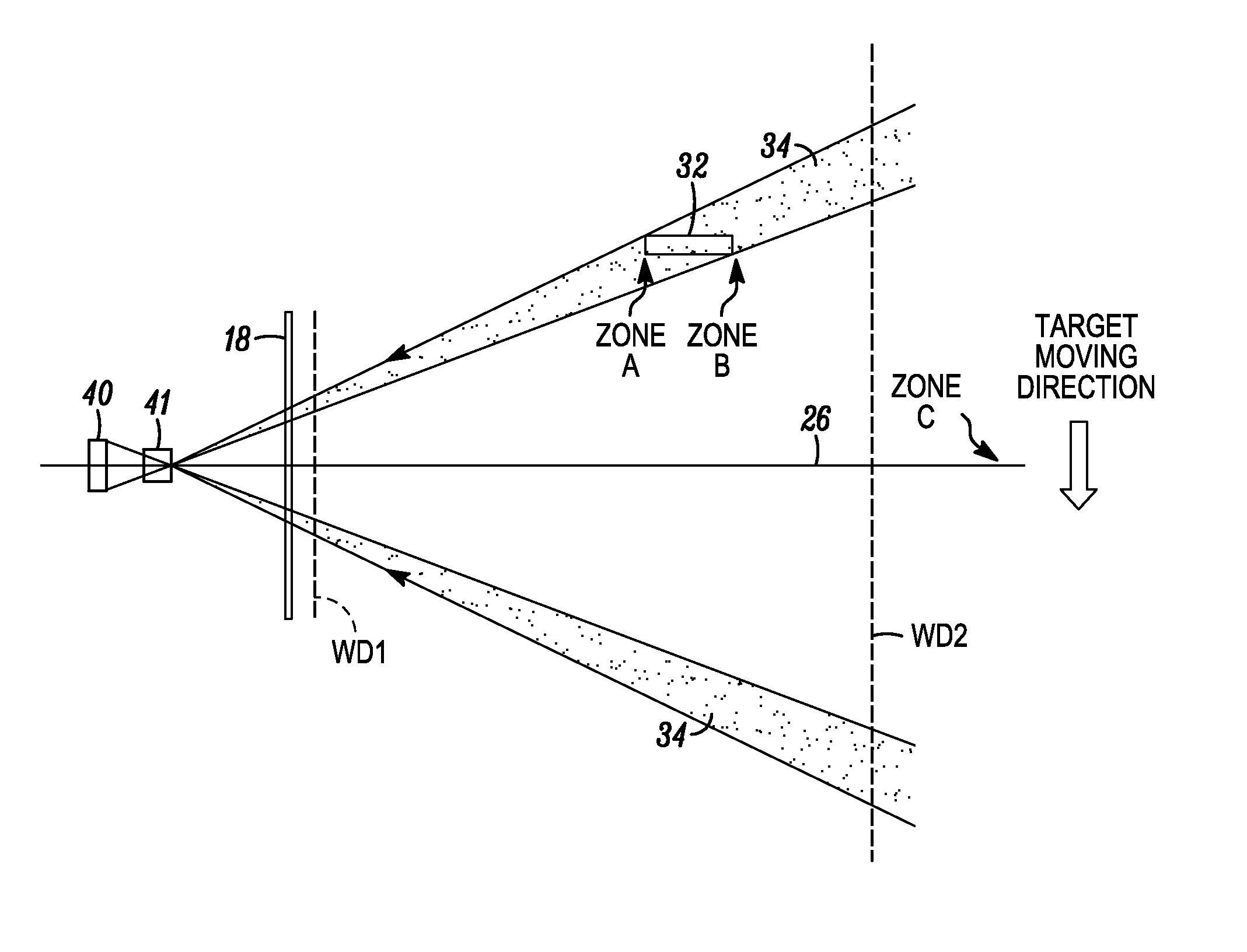
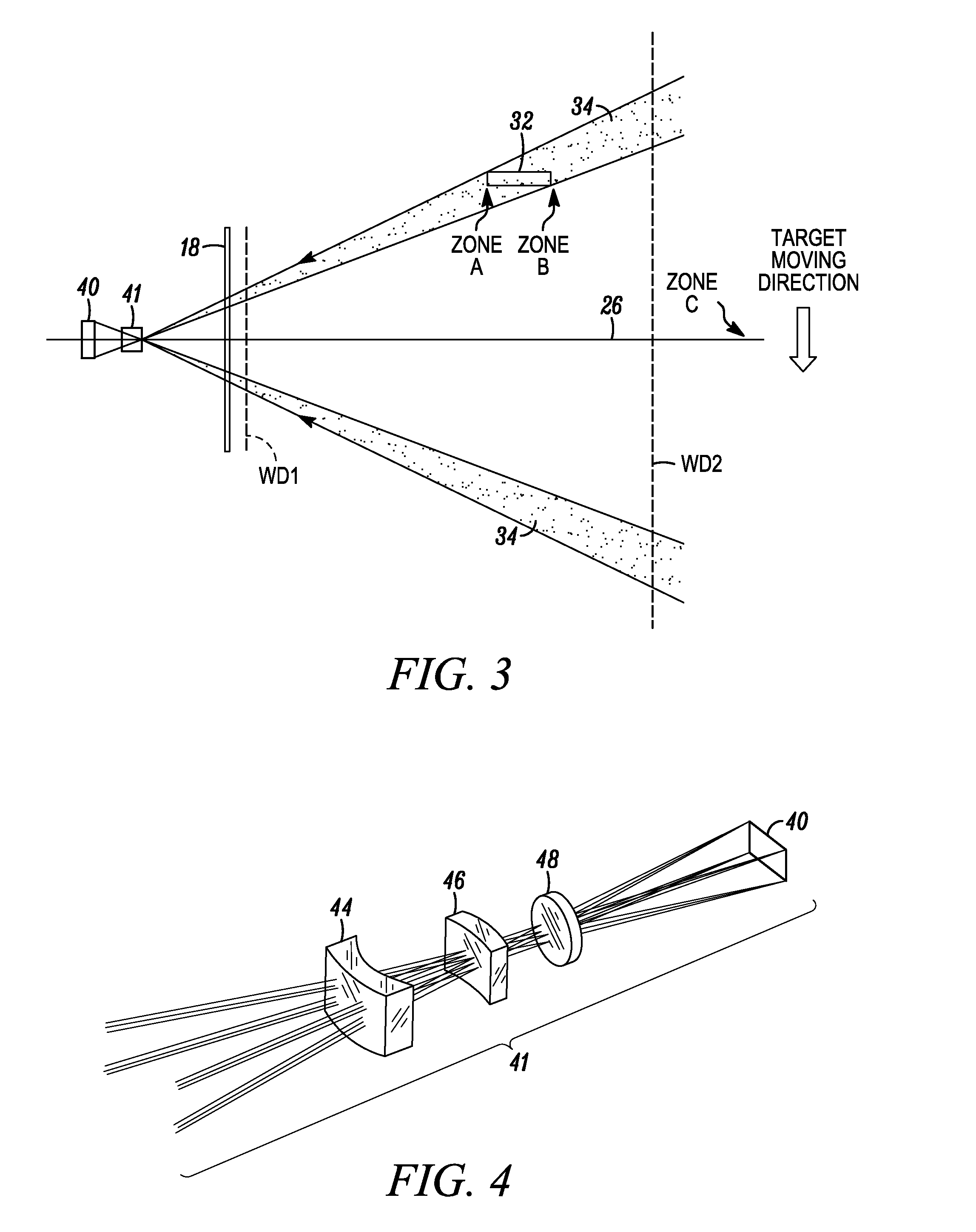
[0008]In accordance with one aspect of this invention, the imaging lens assembly is optically modified for non-uniform magnification within, and for increasing resolution at an outer peripheral region of, the field of view of the array, in an imaging plane generally perpendicular to the optical axis. The magnification at least partly increases in the imaging plane with increasing radial distance away from the optical axis, to enable reading of the target when tilted relative to the optical axis and located at the outer peripheral region of the field of view. Thus, as the magnification is increased in the outer peripheral region in the imaging plane, then there will be more pixels in a given area for sampling the target, a higher PPM, and, as a result, the resolution of the array will be increased along the radial direction in that outer peripheral region. The non-uniform magnification improves the resolution, especially in those cases where the target being read is imaged at a steep, oblique angle relative to the optical axis. Non-uniform magnification partially compensates for any loss in imager array resolution due to the projection effect caused by such a steep, oblique angle and enables the reader to successfully read such tilted targets in the outer peripheral region.
[0010]Advantageously, the optically modified imaging lens assembly gradually increases the magnification in the imaging plane with increasing radial distance away from the optical axis. Put another way, the effective focal length of the imaging lens assembly on the optical axis is shorter than its effective focal length off the optical axis at the outer peripheral region. A longer focal length increases the magnification of the imaging lens assembly. This invention thus redistributes the magnification from an on-axis region to an off-axis region at the outer periphery of the field of view, to enable tilted target symbols at the outer peripheral region to be successfully decoded and read.
[0011]In another modification, the optically modified imaging lens assembly gradually increases the magnification, i.e., increases the effective focal length, in the imaging plane with increasing radial distance away from the optical axis until the outer peripheral region of the field of view is reached, and then gradually decreases the magnification, i.e., decreases the effective focal length, in the imaging plane with increasing radial distance away from the optical axis as the outer peripheral region of the field of view is traversed, to partially compensate for the greater working distance from the window of one end of the tilted target symbol relative to an opposite end of the tilted target symbol. Put another way, the end region of the tilted target symbol, which is closer to the imaging lens assembly as considered along the optical axis, requires less magnification for a successful reading as compared to the opposite end region of the tilted target symbol, which is farther from the imaging lens assembly as considered along the optical axis. The farther end region would therefore appear smaller when projected on the imager array and, hence, would benefit from an increase in magnification.
[0012]In accordance with another feature of this invention, the method of electro-optically reading indicia by image capture is performed by locating the target in a field of view of an array of sensors of a solid-state imager during reading, capturing return light through a window from the target located in a range of working distances along an optical axis of an imaging lens assembly, projecting the captured return light onto the array, and optically modifying the imaging lens assembly for non-uniformly magnification within, and for increasing resolution at an outer peripheral region of, the field of view of the array, in an imaging plane generally perpendicular to the optical axis of the imaging lens assembly, by at least partly increasing the magnification in the imaging plane with increasing radial distance away from the optical axis, to enable reading of the target when tilted relative to the optical axis and located at the outer peripheral region of the field of view.

Problems solved by technology

When the FOV diverges rapidly, the PPM decreases rapidly too, which, in some cases, limits the capability of the reader to decode and read target symbols at far working distances.

Method used


Image

  • Imaging reader with non-uniform magnification within a field of view
  • Imaging reader with non-uniform magnification within a field of view
  • Imaging reader with non-uniform magnification within a field of view

Examples


Embodiment Construction

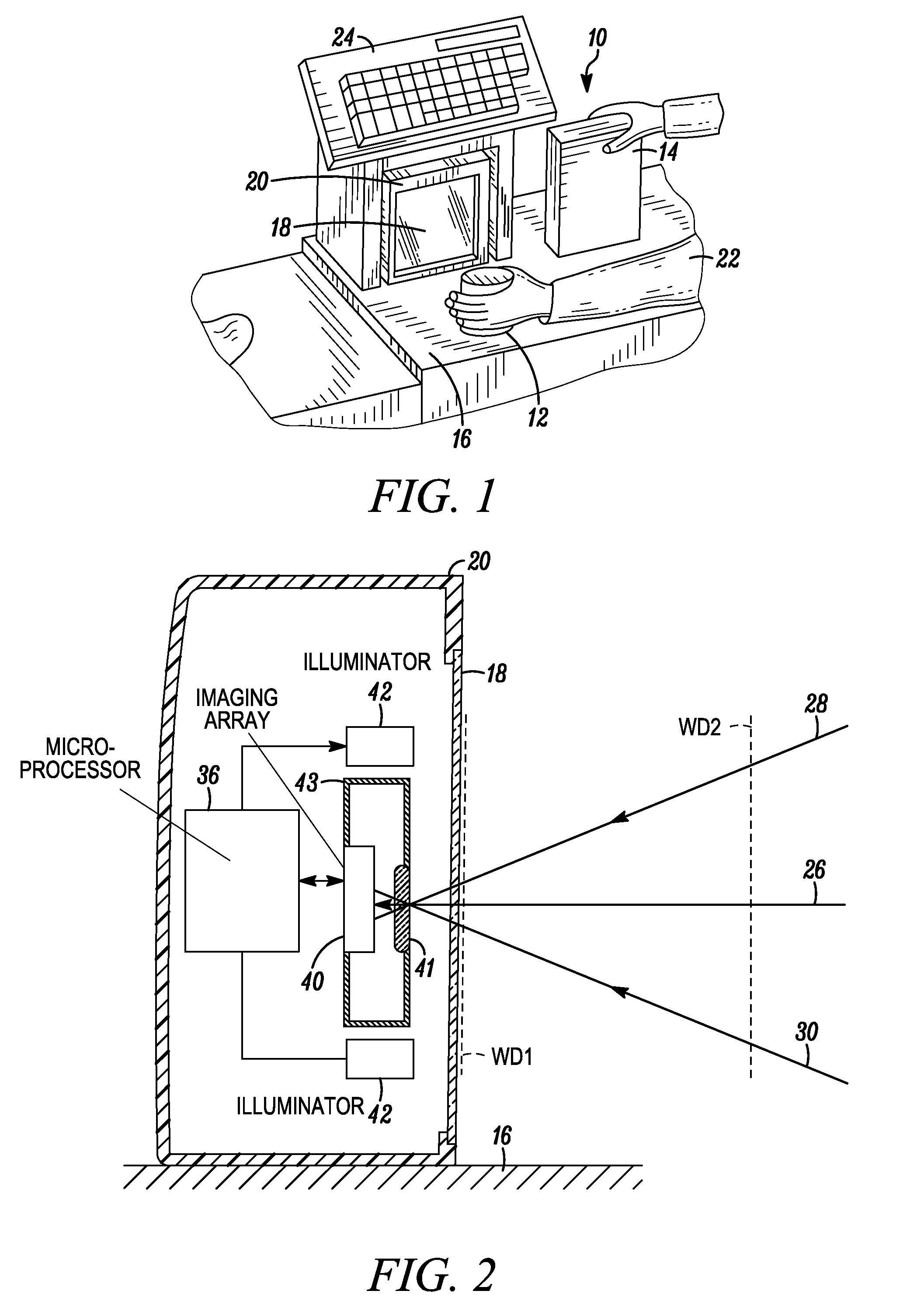
[0021]Reference numeral 10 in FIG. 1 generally identifies an electro-optical reading workstation for processing transactions at a checkout counter of a retail site at which products, such as a can 12 or a box 14, each associated with, and preferably bearing, a target such as a bar code symbol, are processed for purchase. The counter includes a countertop 16 across which the products are presented or slid at a swipe speed past a generally vertical or upright window 18 of a box-shaped imaging reader 20 configured as a vertical slot scanner mounted on the countertop 16. A user, preferably a checkout operator 22, is located at one side of the countertop 16, and the reader 20 is located at the opposite side. A cash / credit register 24 is located within easy reach of the operator. The reader 20 is portable and lightweight and may be picked up from the countertop 16 by the operator 22, and the window 18 may be aimed at a symbol preferably on a product too heavy or too large to be easily pos...


PUM


Abstract

An imaging lens assembly captures return light through a window of a vertical slot scanner from a target located in a range of working distances along an optical axis away from the window, and projects the captured return light onto an array of a solid-state imager. The imaging lens assembly is optically modified for non-uniform magnification within, and for increasing resolution at an outer peripheral region of, a field of view of the array, in an imaging plane generally perpendicular to the optical axis. The magnification is at least partly increased in the imaging plane with increasing radial distance away from the optical axis, to enable reading of the target when tilted relative to the optical axis and located at the outer peripheral region of the field of view.

Description

BACKGROUND OF THE INVENTION[0001]Solid-state imaging readers have been installed in slot scanners or workstations having a horizontally and / or a generally vertically arranged window in supermarkets, warehouse clubs, department stores, and other kinds of retailers for many years, to electro-optically read symbol targets, such as one-dimensional and two-dimensional symbols, particularly a Universal Product Code (UPC) bar code symbol, and non-symbol targets, such as driver's licenses, receipts, signatures, etc., the targets being associated with products to be processed by the slot scanners. An operator or a customer may slide or swipe a product associated with a target in a moving direction across and past a window of the slot scanner in a “swipe” mode. Alternatively, the operator or the customer may momentarily present the target associated with the product to an approximate central region of the window in a “presentation” mode. The choice depends on user preference or on the layout ...

Claims


Application Information

Patent Timeline
Patent Type & Authority Patents(United States)
IPC IPC(8): G06K7/10
CPCG06K7/10722G02B27/0075
Inventor VINOGRADOV, IGORTRAJKOVIC, MIROSLAV
Owner SYMBOL TECH LLC
Why Eureka
Try Eureka