Casing for a moving-blade wheel of turbomachine

a technology of moving blades and turbomachines, which is applied in the direction of machines/engines, stators, liquid fuel engines, etc., can solve the problems of low frequency oscillation, significant losses in the efficiency of rotor wheels, and subject the turbomachine to high stress levels, so as to improve the surge margin, optimize the efficiency of rotor wheels, and reduce contributions.

Active Publication Date: 2014-07-15
SN DETUDE & DE CONSTR DE MOTEURS DAVIATION S N E C M A
View PDF9 Cites 20 Cited by
  • Summary
  • Abstract
  • Description
  • Claims
  • Application Information

AI Technical Summary

Benefits of technology

[0015]The advantage of the invention results from the following two observations: firstly, it is essentially the first groove on the upstream sides of the rotor wheel that contributes to improving the surge margin, the other grooves having decreasing contributions to this improvement as a function of their distance from the first groove; and secondly each of the grooves has an impact that is generally negative on the compression efficiency of the cascade of rotor wheels.
[0016]Thus, in order to optimize simultaneously the efficiency of the rotor wheel and improve the surge margin, the invention gives precedence to the area of the section of the first groove(s) relative to the following grooves (i.e. a group of grooves situated upstream from the other groove(s) that are situated further downstream).
[0017]In general, it is the first groove at the upstream end that has a section area greater than the section area of any of the other grooves. Nevertheless, the invention also covers an embodiment in which the casing presents, from upstream to downstream, two grooves of sections having the same area, followed by two grooves of sections having smaller area, and so on. In the invention, any variation in groove section area may be envisaged, providing the areas of the sections of said circumferential grooves decrease going from upstream to downstream from the first groove to the last groove. This decrease may be regular, as for example when the section area of the grooves decreases linearly from upstream to downstream. In another embodiment, the decrease in the section area of the grooves may equally well take place in steps.
[0018]It should be observed that the grooves under consideration are grooves that are located substantially in register with the blades of the rotor wheel, independently of the shape of the casing upstream and downstream from the rotor wheel.
[0019]In an embodiment, each of the grooves extends substantially in a plane that is perpendicular to the axis of the casing.
[0020]In an embodiment, the depth of the first of said circumferential grooves is greater than the depths of the following grooves situated further downstream.

Problems solved by technology

Surge is a phenomenon of fluid instability that occurs within a compressor, giving rise to low frequency oscillations in the flow, and occurring when the flow rate, supply, pressure, and temperature conditions depart from the normal operating range of the turbomachine.
Since this instability phenomenon usually develops a large amount of energy, it subjects the turbomachine to high levels of stress (statically and dynamically).
This flow gives rise to significant losses in the efficiency of rotor wheels and, in a majority of cases, may give rise to the loss of stability in the compressor (the surge phenomenon).
As a result, the casing is relatively complex to fabricate and is therefore expensive, but without that ensuring that the casing can simultaneously increase surge margin and optimize compression efficiency.

Method used


Image

  • Casing for a moving-blade wheel of turbomachine
  • Casing for a moving-blade wheel of turbomachine

Examples


Embodiment Construction

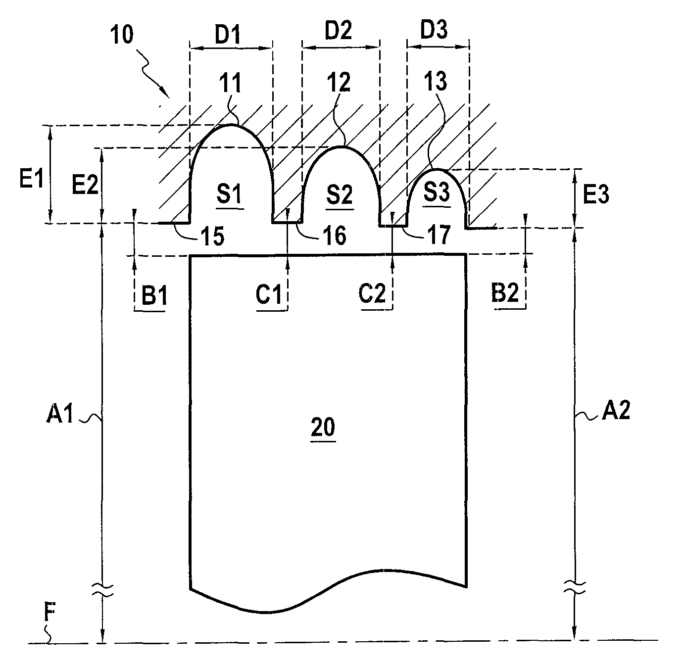
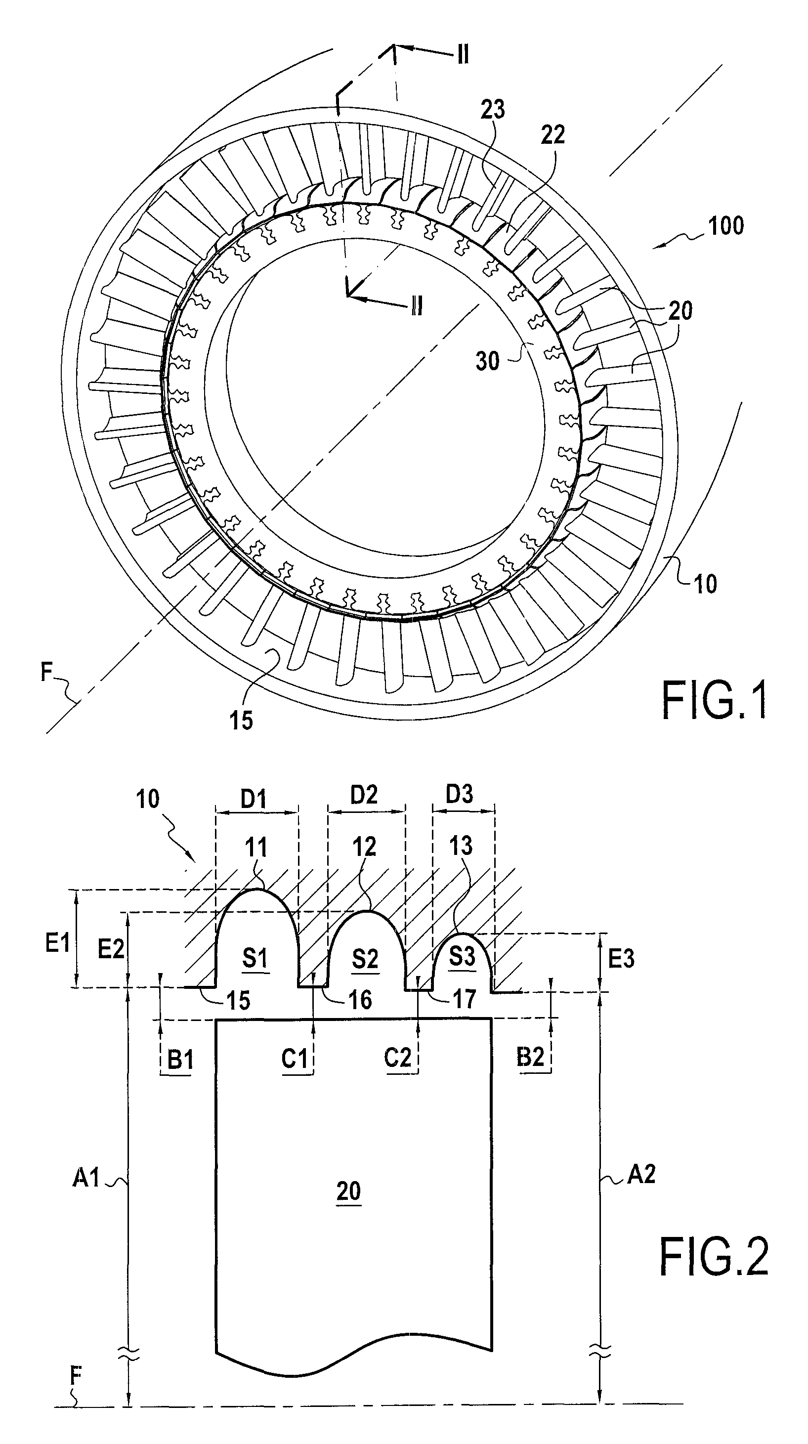
[0033]With reference to FIG. 1, there follows a description of a casing of the invention for rotor wheels.

[0034]FIG. 1 shows a rotor wheel 100. This rotor wheel 100 mainly comprises a rotor disk 30 and blades 20 that are movable in rotation about an axis F inside a stator that is constituted by a stationary casing 10. In the rotor wheel, the disk 30 is a :ring-shaped part having the function of holding and moving the blades 20 in rotation. The blades are generally fastened to the rotor disks via their roots via fasteners of hammer-head or Christmas-tree configuration. Each blade is thus constituted by a root, a platform 22 that constitutes the inside portion of the flow-passing section, and an airfoil 23. The blades may alternatively be made out of the same block of material as the rotor disk, in which the disk is referred to as a one-piece bladed disk. The flow passes substantially along the axis F of the rotor wheel through inter-blade passages located between the airfoils 23 of t...


PUM


Abstract

A casing for a turbomachine rotor wheel includes a plurality of circumferential grooves, each of substantially constant section, with the section areas of the circumferential grooves decreasing from upstream to downstream on going from the first groove to the last groove. By treating the casing in this way, the efficiency of the rotor wheel is optimized and its surge margin is improved.

Description

BACKGROUND OF THE INVENTION[0001]1. Field of the Invention[0002]The invention relates to the field of turbomachine rotor wheels, and in particular compressor wheels. In turbomachines, rotor wheels associated with stator wheels form compressor stages having the function of compressing the fluid passing therethrough. The design and optimization of a cascade of rotor wheels (i.e. a sequence of one or more rotor wheels), e.g. for a compressor, requires two objectives to be taken into account.[0003]2. Description of the Related Art[0004]The first objective is to have good compression efficiency. Compression efficiency may be defined as the ratio of the energy that would ideally be imparted to the fluid by isentropic compression from upstream to downstream of the cascade of rotor wheels divided by the energy actually imparted to the fluid. (In the present document, upstream and downstream are defined relative to the normal flow direction of the fluid through the cascade of rotor wheels.)[...

Claims


Application Information

Patent Timeline
Patent Type & Authority Patents(United States)
IPC IPC(8): F03B11/02F01D25/24F04D29/16F04D29/42F04D29/52
CPCF04D29/526F04D29/164F04D29/685
Inventor BRUNET, ANTOINE ROBERT ALAINDOMERCQ, OLIVIER STEPHANEJABLONSKI, LAURENTPERROT, VINCENT PAUL GABRIEL
Owner SN DETUDE & DE CONSTR DE MOTEURS DAVIATION S N E C M A
Why Eureka
Try Eureka