Packing system and method for chromatography columns

a chromatography column and column technology, applied in the field of system for packing chromatography columns, can solve the problems of axial heterogeneity, poor bed stability, and uneven column efficiency, and achieve the effects of improving bed stability, high mechanical complexity, and high column efficiency

Active Publication Date: 2014-07-15
CYTIVA BIOPROCESS R&D AB
View PDF27 Cites 9 Cited by
  • Summary
  • Abstract
  • Description
  • Claims
  • Application Information

AI Technical Summary

Benefits of technology

[0019]The main advantage of the invention is that the packed bed is prepared by the axial compression method yielding advantages of improved bed stability and high column efficiency without the need for high mechanical complexity in the column construction required by conventional solutions for axial compression columns. This allows for a substantial cost reduction.
[0020]Yet another advantage of the method of the invention is that it is compatible with low-pressure fluid handling equipment (e.g. a peristaltic pump) as the compression is achieved primarily by the external drive means, such as a compression frame, rather than by the high pressures required by flow compression.
[0021]Yet another advantage of the method of the invention is that the packing / filling of the column can be performed as a closed system, which means that the column may even be filled / packed under aseptic conditions starting from a pre-sterilized column and pre-sterilized chromatography medium. The method can therefore be used on “ready-to-process” or “disposable” columns.
[0022]Still a further advantage is that the chromatography column is scalable (i.e. increasing or decreasing the column size leads to a predictable performance). This is due to the fact that the filling of the column via the slurry nozzle is done prior to the axial compression step at an elevated adapter position. This allows for homogeneous distribution of the slurry over the cross-sectional area of the column compared to flow packing using a nozzle based on one designed with fixed end cells (for example, see U.S. Pat. No. 6,524,484). For the latter, the packing has to be performed at a constant bed height, the target bed height, which may lead to radial gradients in packed bed density and compression, respectively.
[0023]Another advantage of the method of the invention is that the column does not need to be as long as axial compression columns of the prior art because not all of the slurry needs be introduced into the column prior to the commencement of bed formation.
[0024]A further advantage of the invention is that a minimum adapter (end unit) stroke is required compared to systems using known methods and thus allows for a more compact construction.

Problems solved by technology

If the packed bed is not homogeneous and stable a deleterious effect will be experienced for chromatographic separations performed on the bed.
The flow packing method has the disadvantage that beds of packing material compressed in this manner are axially heterogeneous during the flow compression step yielding highest compression close to the outlet of the column and zero compression at the top of the packed bed.
The gradient in bed compression inherent to this method may result in poor bed stability and poor column efficiency depending on the type of medium and the packed bed geometry.
Standard methods of flow packing may not be suitable for the wide bore columns used in preparative chromatography.
Among other factors, it is often undesirable to design equipment that requires application of a packing flow rate and thus a packing pressure substantially higher than the pressure required for subsequent operation.
Radial gradients in bed compression and bed voidage occur with both methods described, which is due to wall friction effects.
A disadvantage of axial compression is that columns packed using this method require a means for moving the end cell and a means for controlling this movement.
As these are attached to or built in to the column, the cost and mechanical complexity of axial compression columns is substantially higher than for flow packing columns.

Method used


Image

  • Packing system and method for chromatography columns
  • Packing system and method for chromatography columns
  • Packing system and method for chromatography columns

Examples


Embodiment Construction

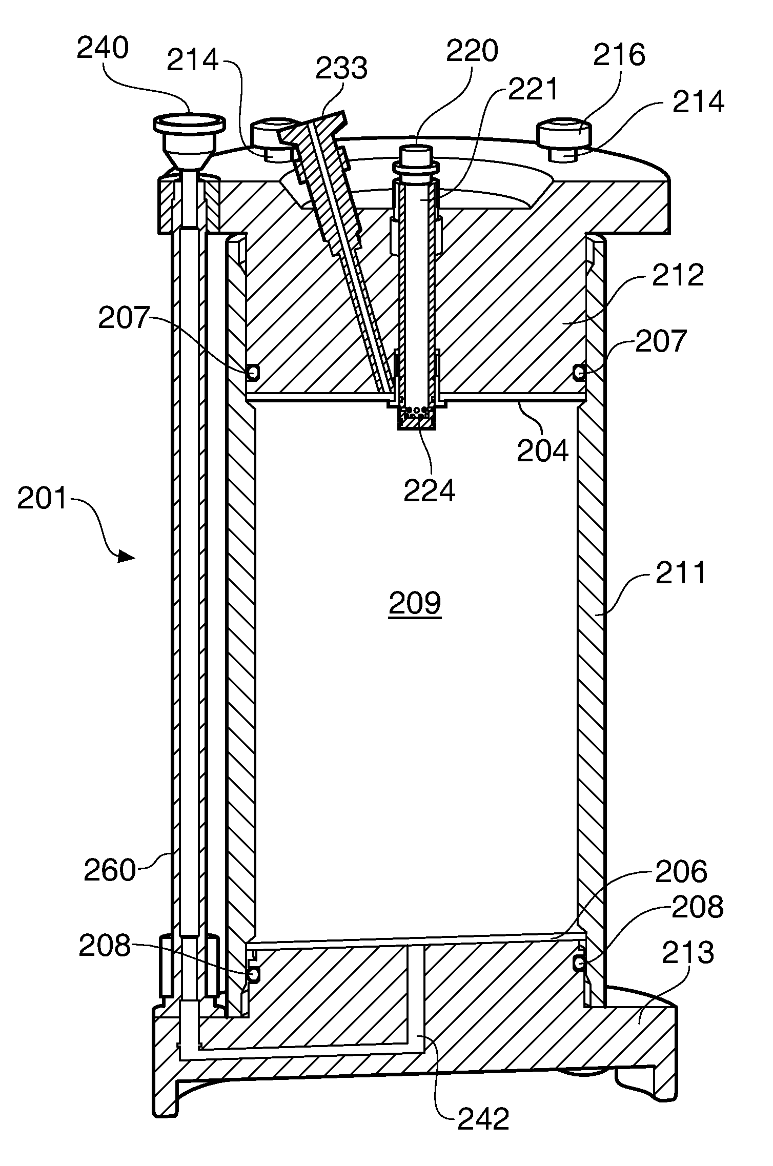
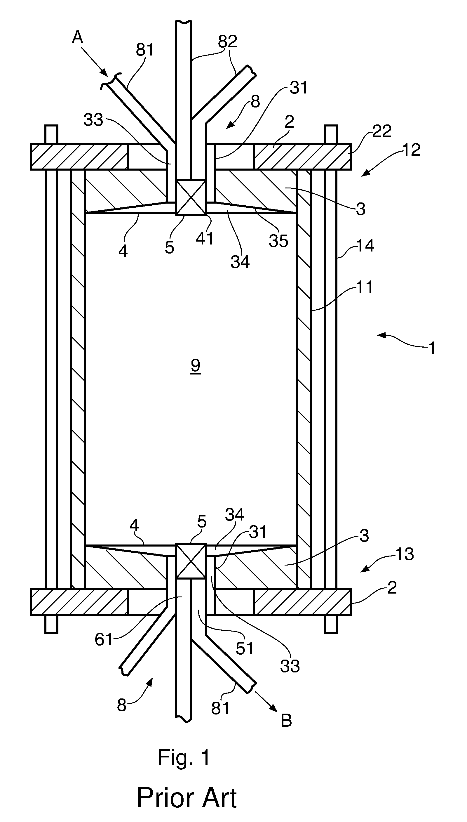
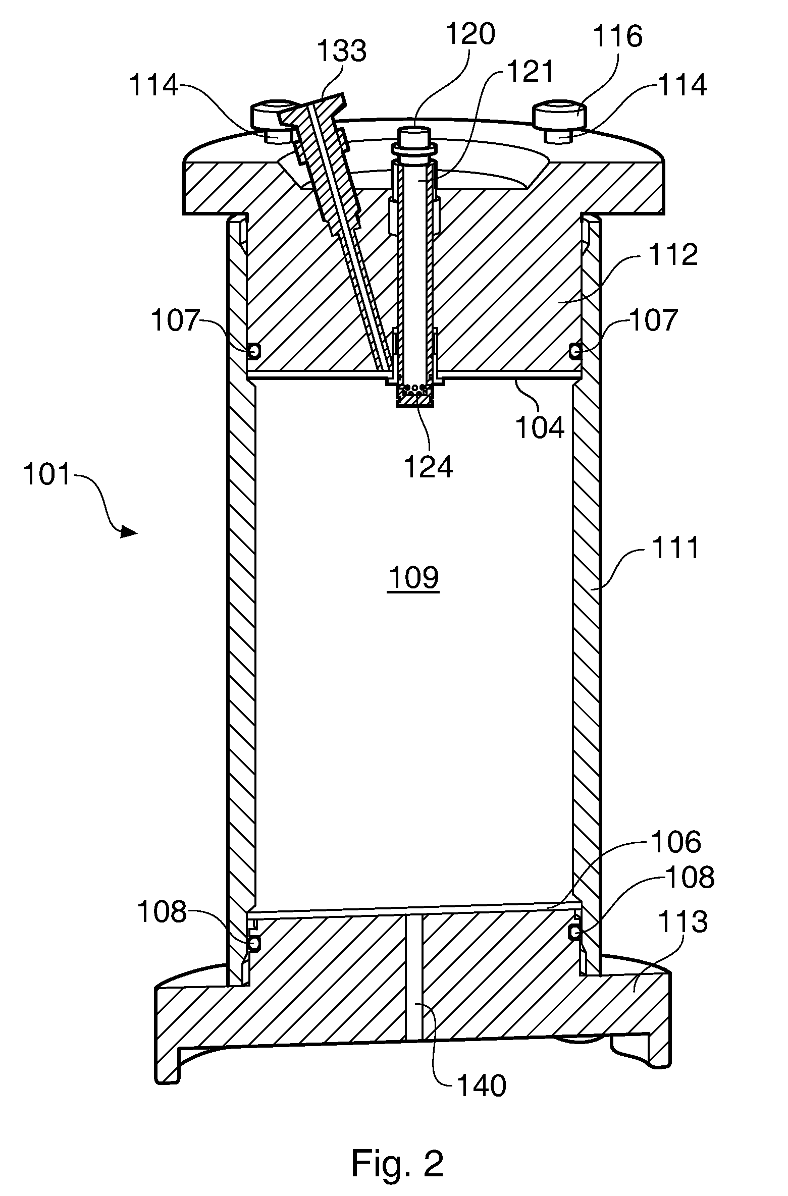
[0051]FIG. 1 shows schematically the general components of a chromatography column 1 as known from the prior art (for example, see U.S. Pat. No. 6,524,484). The column has a cylindrical fluid-impermeable side wall 11, e.g. of stainless steel or a high-strength / reinforced polymeric material which may be translucent. The open top and bottom ends of the side wall 11 are closed by top and bottom end assemblies or units 12, 13. Each end unit has a fluid-impermeable end plate 3 fitting sealingly to plug the opening of the cylindrical wall 11, and preferably made of stainless steel or high-strength engineering plastics material, e.g. polypropylene. The end plates are backed up by retaining metal plates 2 bearing against their outer surfaces and projecting radially beyond the side wall as retaining flanges 22 through which adjustable tension rods 14 are secured. These link the top and end assemblies 12, 13 and help the construction to withstand high fluid pressures.

[0052]Each end plate 3 ha...


PUM

PropertyMeasurementUnit
column diameteraaaaaaaaaa
particle diameteraaaaaaaaaa

Abstract

The invention relates to a system for packing chromatography columns with a chromatography medium and packing method for use in such columns. In particular, the invention relates to a method and system for packing chromatography columns which utilizes an external drive means to compress a bed of particulate medium to a target bed height.

Description

CROSS-REFERENCE TO RELATED APPLICATIONS[0001]This application claims priority to patent application number 0704603.0 filed in Great Britain on Mar. 9, 2007; the disclosure of which is incorporated herein by reference in its entirety.FIELD OF THE INVENTION[0002]The present invention relates to a system for packing chromatography columns with a chromatography medium and packing method for use in such columns. More specifically, the invention relates to packing systems and methods for improving the packing of chromatography media into chromatography columns.BACKGROUND OF THE INVENTION[0003]Columns used in liquid chromatography typically comprise a tubular body enclosing a porous chromatography medium through which a carrier liquid flows, with separation taking place by material collection between the carrier liquid and solid phase of the porous medium. Prior to any separation process, the bed has to be prepared starting from the slurry of particles that has to be introduced into the co...

Claims


Application Information

Patent Timeline
Patent Type & Authority Patents(United States)
IPC IPC(8): B01D15/08B01D15/20B01D15/22C02F1/28G01N30/60
CPCB01D15/206B01D15/22G01N30/56G01N30/6021G01N30/603G01N30/606G01N2030/565
Inventor GEBAUER, KLAUS
Owner CYTIVA BIOPROCESS R&D AB
Why Eureka
Try Eureka