Method for automatic location identification of electronic devices on agricultural implements

a technology of electronic devices and agricultural implements, applied in the field of electronic control systems, to achieve the effect of high system control resolution

Active Publication Date: 2014-07-15
LEADER TECH
View PDF5 Cites 21 Cited by
  • Summary
  • Abstract
  • Description
  • Claims
  • Application Information

AI Technical Summary

Benefits of technology

[0013]Therefore, it is a primary object, feature, or advantage of the present invention to improve over the state of the art.
[0014]It is a further object, feature, or advantage of the present invention to provide for the automatic assignment of an address to indicate the physical or logical location of an electronic device on an agricultural vehicle or implement.
[0015]It is a still further object, feature, or advantage of the present invention to provide for the use of multiple tiers.
[0016]One or more of these and / or other objects, features, or advantages of the present invention will become apparent to those skilled in the art upon reference to the following specification, drawings, and claims. No single embodiment of the invention need meet each and every object, feature, or advantage provided herein and the present invention is not to be limited to or by these objects, features and / or advantages.
[0017]The present invention is a method for automatic location (or index) identification of electronic devices used for control and / or data collection on agricultural implements and vehicles. In particular, the method uses a serial control line passed through each device and one or more shared data buses between devices to allow each device to automatically determine its unique physical or logical address. This unique address is used by other devices to have individual communication with a single device using the shared data bus that connects to the devices.
[0018]The present invention intends to overcome the difficulties encountered heretofore in the assignment of electronic device addresses to indicate physical or logical location on an agricultural vehicle or implement. To that end, a design is presented that uses address control lines in each device and a communication process on one or more shared data buses so each device can determine its own physical or logical location. This design automatically assigns a device address without requiring any special action prior to installation or requiring interaction with an external device that assigns the device address.

Problems solved by technology

The problem with these methods is that they require special action on the device (from either an operator / technician or an external device) or a specially-designed wiring harness to assign an address so it functions properly.

Method used


Image

  • Method for automatic location identification of electronic devices on agricultural implements
  • Method for automatic location identification of electronic devices on agricultural implements
  • Method for automatic location identification of electronic devices on agricultural implements

Examples


first embodiment

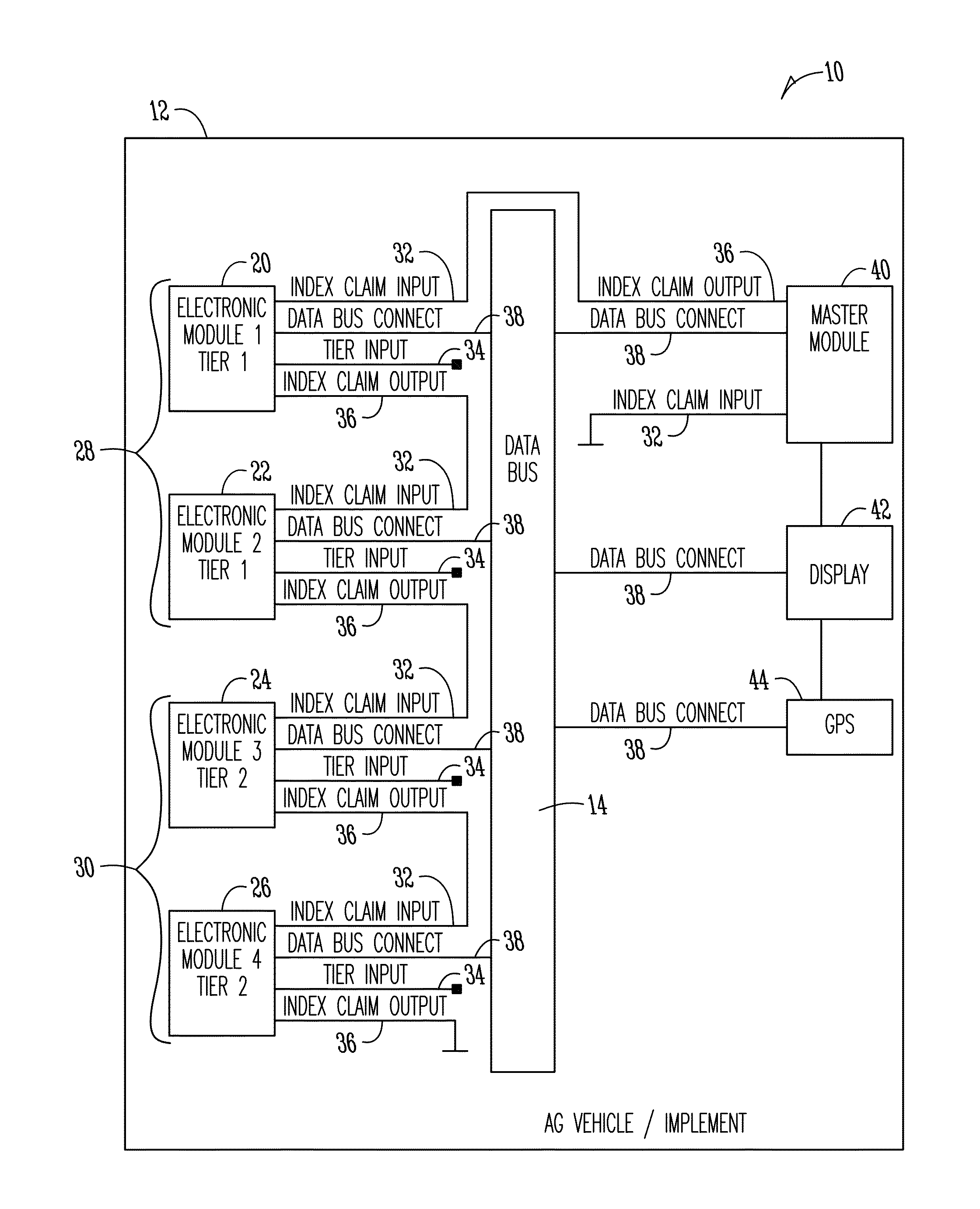
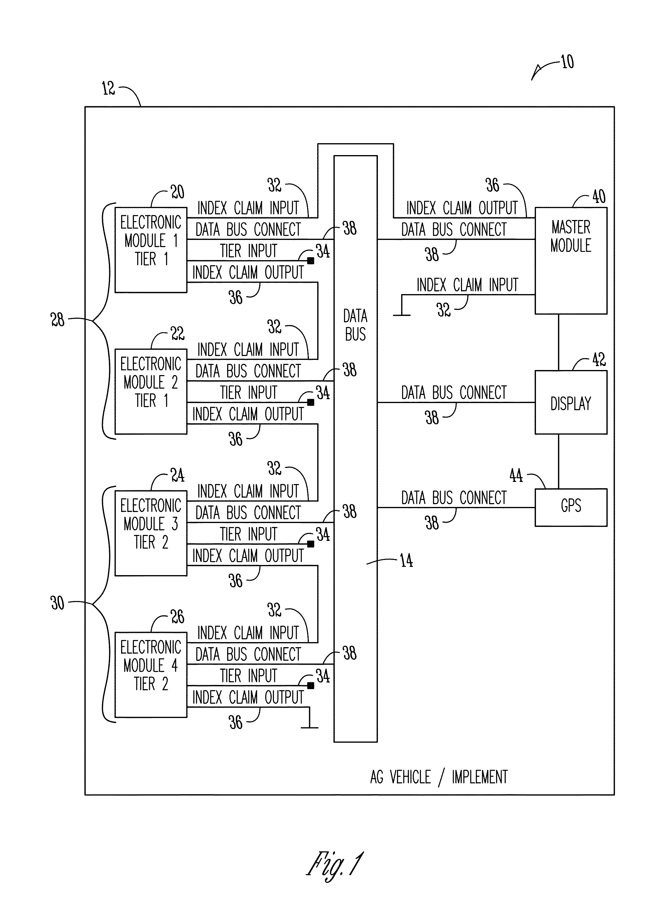
[0041]In the first embodiment shown in FIG. 3, the liquid control system consists of a liquid control master module 133 and four section control modules 101, 109, 117, and 125. The four section control modules represent two tiers. Each module is connected to electrical power 148 and electrical ground 149. For section control module 101, the electrical power connection is input line 106 and the electrical ground connection is input line 107. Each module is also connected to the common data bus (ECU DATA BUS), which is a CAN bus. For section control module 101, the common data bus is connected to input / output lines 103 (CAN High) and 104 (CAN Low).

[0042]Each module has an index claim input. These are input lines 102, 110, 118, 126, and 134. In this embodiment of the invention, if the voltage on the index claim input is greater than half the electrical power input voltage, the input is considered to be logic high. Likewise, if the input voltage is less than half the electrical power in...

second embodiment

[0047]In the second embodiment shown in FIG. 4, the liquid control system consists of a liquid control master module 200 (ECU-9) and two liquid control slave modules 186 (ECU-7) and 193 (ECU-8). The system also includes six section control modules 150 (ECU-1), 156 (ECU-2), 162 (ECU-3), 168 (ECU-4), 174 (ECU-5), and 180 (ECU-6). The six section control modules represent two tiers. Each module is connected to electrical power 210 and electrical ground 211. For simplicity, the electrical power and ground is drawn as a single POWER AND GROUND bus. For section control module 150, the POWER AND GROUND bus connection is input element 154. There are four data buses in the system, which are implemented as CAN buses: DATA BUS 1, DATA BUS 2, DATA BUS 3, and DISPLAY DATA BUS. For simplicity, the CAN High and CAN Low lines of each data bus are drawn as a single thick line. DATA BUS 1 connects bus elements 152, 158, and 187 and connects modules 150, 156, and 186. DATA BUS 2 connects bus elements ...


PUM


Abstract

A system for performing agricultural operations includes a plurality of electronic modules for use on an agricultural machine, the plurality of electronic modules configured for controlling agricultural operations associated with the agricultural machine, at least one shared data bus operatively connected to each of the plurality of electronic modules, wherein each of the plurality of electronic modules being configured to monitor the at least one shared data bus and determine an unused location for itself and claim the location, wherein the system uses the location of each of the plurality of electronic modules in controlling the agricultural operations associated with the agricultural machine. A method provides for automatic assignment of a physical (or logical) address to each of a plurality of devices mounted on either a vehicle or implement used for an agricultural operation.

Description

FIELD OF THE INVENTION[0001]The present invention relates to electronic control systems associated with agricultural machines such as agricultural implements and / or agricultural vehicles. In particular, the present invention relates to electronic control systems on agricultural machines which include a plurality of different electronic modules which need to have unique addresses.BACKGROUND OF THE INVENTION[0002]The nature of many agricultural implements (especially for grain crops) is to have a series of devices (discs, shovels, row units, spray nozzles, etc.) that are spanned across a bar or boom that runs perpendicular to the axis of motion of the tractor or other vehicle. When the implement is used, the devices run at parallel intervals (which may or may not be evenly spaced) in relation to the direction of forward motion of the vehicle. If the devices are “active” (driven or controlled by external means to perform a function), they are usually controlled by one or more of the fo...

Claims


Application Information

Patent Timeline
Patent Type & Authority Patents(United States)
IPC IPC(8): G06F7/70
CPCH04L61/2038A01B79/005G06F12/0669A01M7/0089A01C23/007H04L67/12H04W4/023H04L61/20H04L61/6027H04L61/5038H04L2101/627
Inventor WOODCOCK, ANTHONY, RYAN
Owner LEADER TECH
Why Eureka
Try Eureka