Scanning probe microscope having support stage incorporating a kinematic flexure arrangement

a scanning probe and support stage technology, applied in the field of microscopy, can solve the problems of affecting the accuracy of displacement measurements, lack of atomic and subatomic probe sensitivity, and sensor drawbacks, and achieve the effects of low noise, high bandwidth, and low power dissipation

Active Publication Date: 2014-07-15
BRUKER NANO INC
View PDF15 Cites 2 Cited by
  • Summary
  • Abstract
  • Description
  • Claims
  • Application Information

AI Technical Summary

Problems solved by technology

While a number of sensors and measurement techniques have been developed to precisely measure the displacement of the probe during the scanning of a sample, these sensors suffer from a number of drawbacks.
For instance, many sensors have been found to lack the necessary sensitivity for atomic and subatomic probes, are unduly large or have a limited sensing range, or are highly susceptible to interference that can negatively impact the precision of the displacement measurements.

Method used


Image

  • Scanning probe microscope having support stage incorporating a kinematic flexure arrangement
  • Scanning probe microscope having support stage incorporating a kinematic flexure arrangement
  • Scanning probe microscope having support stage incorporating a kinematic flexure arrangement

Examples


Embodiment Construction

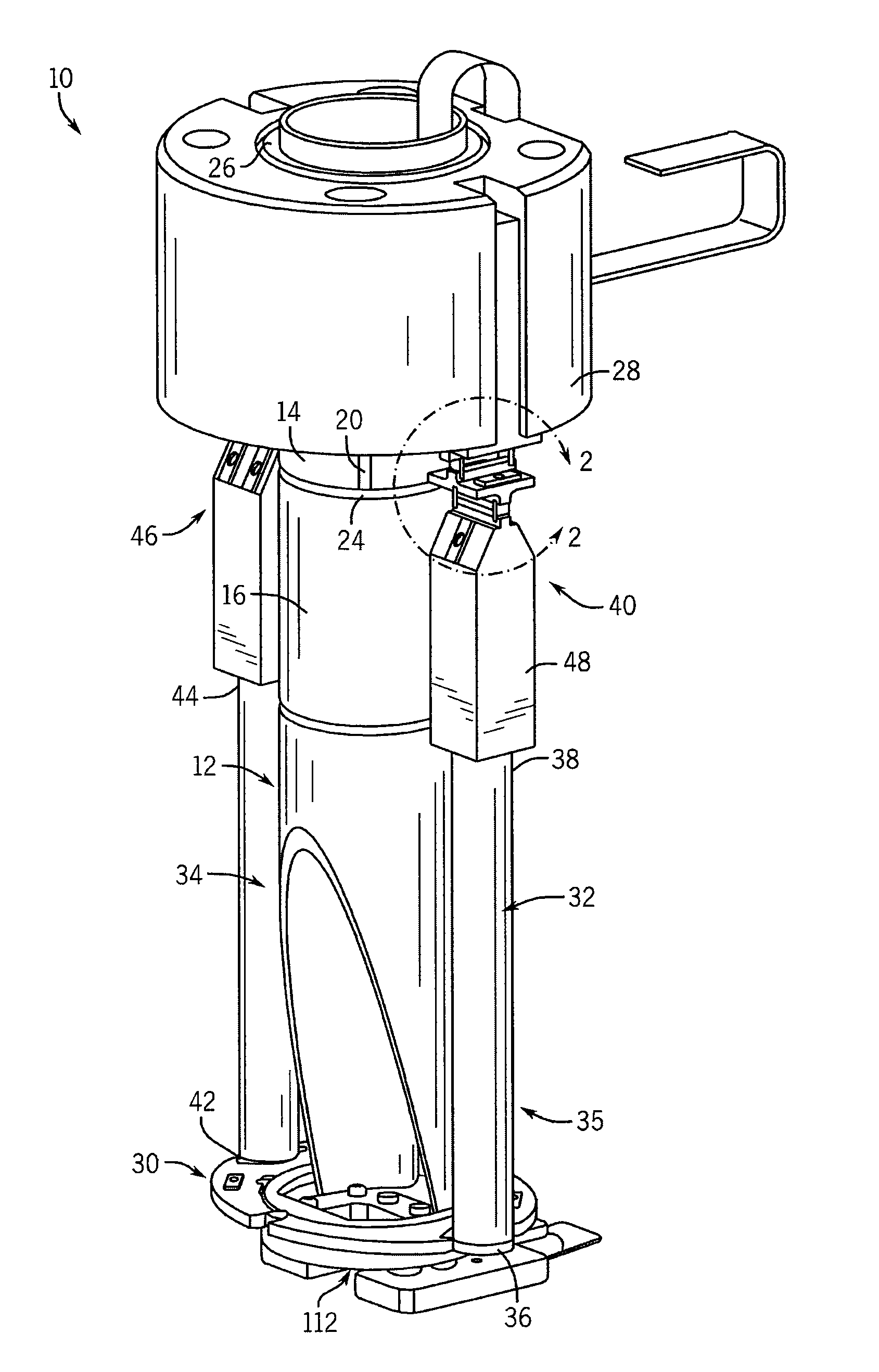
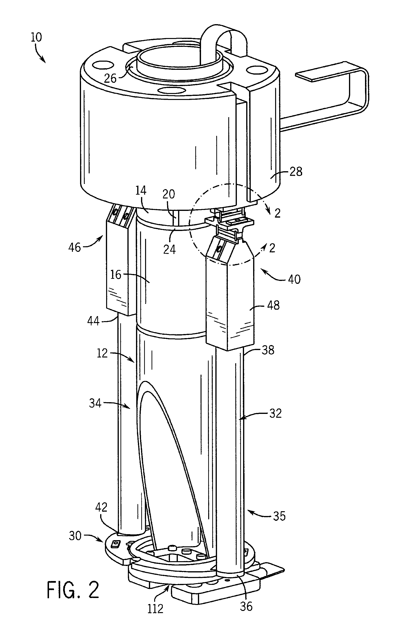
[0019]FIGS. 1-5 show a stage or scan head 10 according to one embodiment of the invention. The scan head 10 forms part of a SPM in the form of an atomic force microscope (AFM) 200 (FIG. 1) that is well-suited for scanning and imaging of objects in the atomic and subatomic scale. It is understood, however, that the scan head 10, and other scan heads falling within the scope of the appended claims, may be used with other instruments as well.

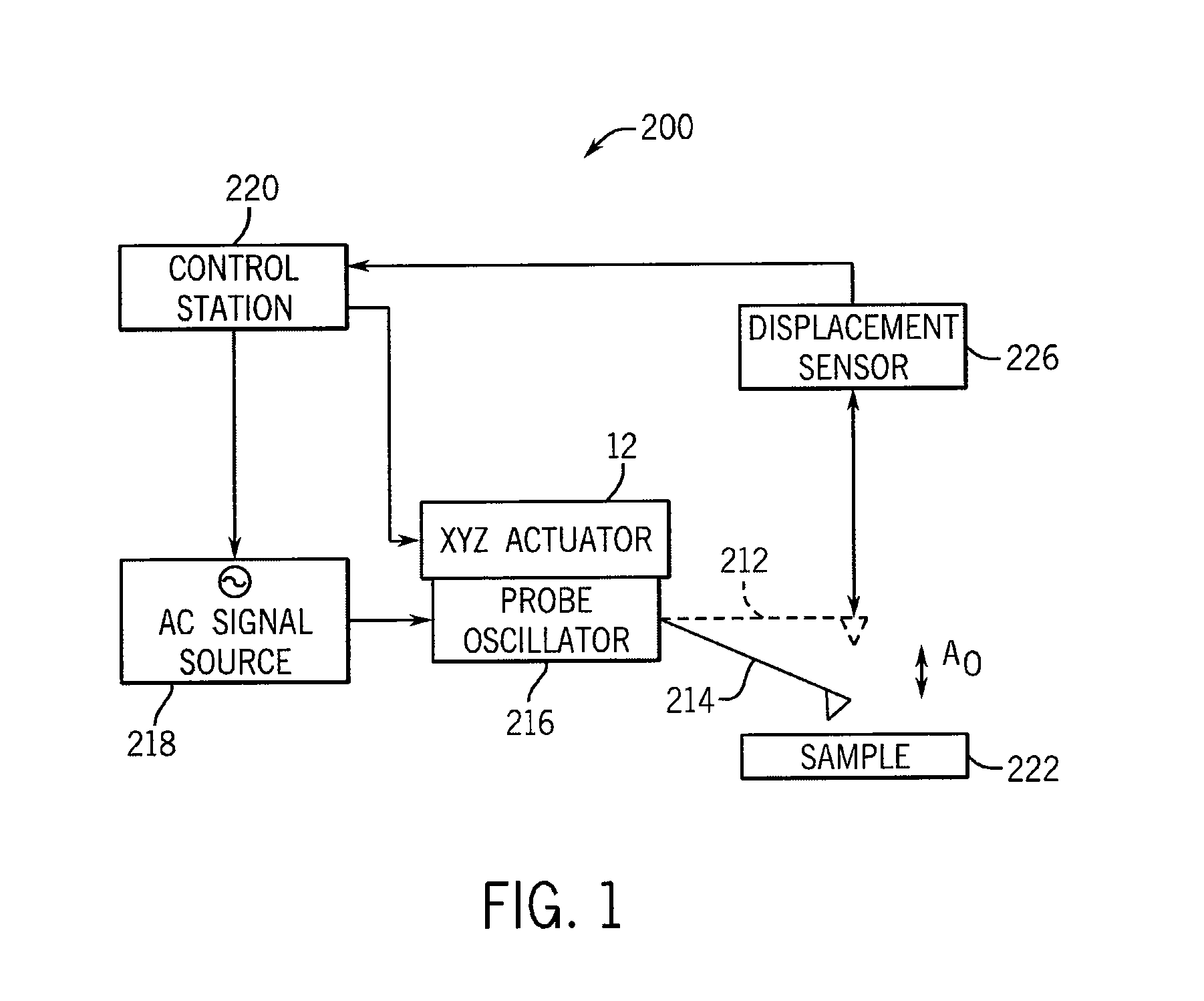
[0020]Referring to FIG. 1, AFM 200 of this embodiment includes, among other components, an actuator assembly, XYZ actuator assembly or scanner 112, and a control station 220. The scanner 112 is mounted over a sample 222 and bears a probe 212 on its lower, moving end. Probe 212 has a cantilever 214 and a tip mounted on the free end portion of the cantilever 214. The probe 212 is coupled to an oscillating actuator or drive 216 that is used to drive probe 212 to oscillate, in this case, at or near the probe's resonant frequency. Commonly, an electroni...


PUM


Abstract

A scanning probe microscope (SPM) has a piezoelectric actuator-based tube scanner to which a probe is attached and which is moveable in three planes by the application of a voltage to the piezoelectric tube. A set of flexures flex with the displacement of the tube and strain gauges attached to the flexures measure the flex of the flexures to provide feedback as to the displacement of the tube during the scanning of an object. The strain gauges and flexures form a kinematic sensing frame or arrangement in which a single constraint is provided for each degree of freedom and in which the constraints are at least substantially orthogonal to one another.

Description

CROSS-REFERENCE TO A RELATED APPLICATION[0001]The present application claims the benefit of U.S. Ser. No. 61 / 256,073, filed Oct. 29, 2010, the disclosure of which is incorporated herein in its entirety.FIELD OF THE INVENTION[0002]The present invention relates generally to microscopy and, more particularly, to an electromechanical scanning device, such as a scanning probe microscope (SPM), having an apparatus that measures the displacement of the scanning device during scanning of a sample.BACKGROUND OF THE INVENTION[0003]Electromechanical scanning devices, such as SPMs and force scanning probe microscopes (FSPM), are commonly used to generate an image of a characteristic or sample using a probe that scans or otherwise interacts with the sample. A scanner moves the probe and / or sample relative to one another in a horizontal or X-Y plane to position the probe at a desired location on the sample, and the probe and / or sample are moved relative to one another in a vertical or Z direction...

Claims


Application Information

Patent Timeline
Patent Type & Authority Patents(United States)
IPC IPC(8): G01Q10/00G01Q10/06B82Y35/00G01Q10/04
CPCG01Q10/065B82Y35/00G01Q70/04G01Q10/04G01Q10/00G01Q20/00G01Q30/00
Inventor MASSER, CARL
Owner BRUKER NANO INC
Why Eureka
Try Eureka