Facing element for use in a stabilized soil structure

a technology of facing elements and stabilized soils, applied in soil preservation, artificial islands, bulkheads/piles, etc., can solve the problems of limiting the efficiency affecting the stability so as to improve the pulling resistance of the anchoring region

Active Publication Date: 2014-07-29
TERRE ARMEE INT
View PDF17 Cites 12 Cited by
  • Summary
  • Abstract
  • Description
  • Claims
  • Application Information

AI Technical Summary

Benefits of technology

[0016]Said shape and geometric characteristics of the facing element make possible to avoid breaking of the cylindrical core according to a bending mode when being pulled by fill reinforcement strips. The inventors have noticed that the cylindrical cores of said facing elements break according to a shearing mode.
[0020]One can then advantageously design stabilized soil structures with said facing elements. According to an embodiment, one can significantly reduce the thickness of the facing element according to the invention in comparison with a facing element as previously known and obtain similar pulling resistance for both facing elements.
[0031]According to an embodiment of said stabilized soil structure, a surface of the said strip forming the open loop contacts and presses substantially the whole external periphery of the cross section of the first part of the cylindrical core, and at least a part of the external periphery of the cross section of the second part of the cylindrical core. According to said embodiment, compression load is applied at least partly around the cylindrical core. Said embodiment helps to further improve the pulling resistance of the anchoring region.

Problems solved by technology

Once the structure is complete, the reinforcements distributed through the fill transmit high loads, in some cases of up to several tons.
Although preceding facing elements are widely and effectively used, one has noticed that their cylindrical cores usually break according to a bending mode when being pulled by fill reinforcement strips.
This breaking mode may limit the efficiency of the anchoring region and has to be taken into account when designing a stabilized soil structure comprising said facing elements.

Method used


Image

  • Facing element for use in a stabilized soil structure
  • Facing element for use in a stabilized soil structure
  • Facing element for use in a stabilized soil structure

Examples


Embodiment Construction

[0042]Skilled artisans appreciate that elements in the figures are illustrated for simplicity and clarity and have not necessarily been drawn to scale. For example, the dimensions of some of the elements in the figures may be exaggerated relative to other elements to help improve the understanding of the embodiments of the present invention. Like reference characters in the different figures refer to similar parts.

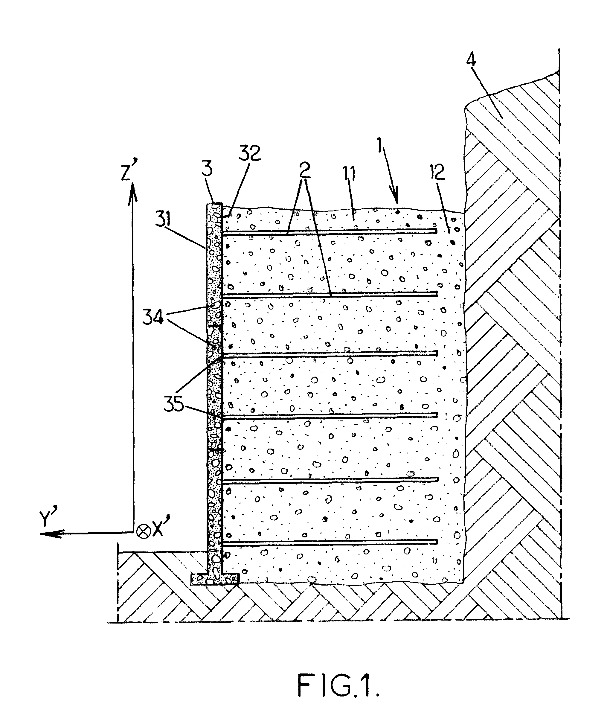
[0043]FIG. 1 illustrates the application of the invention to the building of a stabilized soil retaining wall or stabilized soil structure before a face 4. A compacted fill 1, in which reinforcements 2 are distributed, is delimited on the front side of the structure by a facing 3 formed by juxtaposing facing elements such as prefabricated elements 34 in the form of panels, and on the rear side by the soil against which the stabilized soil structure wall is erected.

[0044]The facing 3 extends along a longitudinal direction X′ and an elevation direction Z′. The facing 3 may b...


PUM


Abstract

A facing element (34) for use in a stabilized earth structure where the facing element comprises at least a hollow part (37) with an opening (36) on the rear face (32) wherein a cylindrical core (5) is arranged at least partly in the hollow part (37) and consists of two continuous parts (51, 52) where the first part (51) has a continuously decreasing size to an extremity (54) and the second part (52) has a continuously constant and / or decreasing size to an extremity (55) and wherein: L2≧1.2×d1; and A>0.24×d12; wherein: L2 is the distance between the extremity (54) of the first part (51) and the rear face (32); d1 is the width of the cylindrical core (5) at the extremity (54) of the first part (51); A is the area of the cross section of the cylindrical core (5) in the plane (X, Z). Improved anchoring properties are accordingly obtained.

Description

[0001]This Application is a 35 U.S.C. §371 National Stage Entry of International Application No. PCT / EP2011 / 054572, filed Mar. 24, 2011, and claims the benefit of European Application No: 10305342.7, filed Apr. 2, 2010, which is incorporated by reference in its entirety herein.BACKGROUND OF THE INVENTION[0002]The present invention relates to a facing element for use in a stabilized soil structure. It also relates to a stabilized soil structure comprising said facing element and to a method for erecting a stabilized soil or reinforced earth structure. This building technique is commonly used to produce structures such as retaining walls, bridge abutments, etc.[0003]A stabilized soil structure combines a compacted fill, a facing, and reinforcements usually connected to the facing. The reinforcements are placed in the soil with a density dependent on the stresses that might be exerted on the structure, the thrust forces of the soil being reacted by the soil-reinforcements friction.[000...

Claims


Application Information

Patent Timeline
Patent Type & Authority Patents(United States)
IPC IPC(8): E02D29/02
CPCE02D29/0241E02D29/0225E02D29/025
Inventor CARIOU, RICHARD
Owner TERRE ARMEE INT
Why Eureka
Try Eureka