

Cascaded PLL for reducing low-frequency drift in holdover mode
a holdover mode and pll technology, applied in the field of integrated circuits, can solve the problems of affecting the operation of the clock generator, the frequency of the clock signal generated in holdover mode may still drift, and the requirement of holdover, so as to reduce the frequency drift, the effect of increasing the temperature dependence and reducing the jitter
- Summary
- Abstract
- Description
- Claims
- Application Information
AI Technical Summary
Benefits of technology
Problems solved by technology
Method used
Image

Examples
Embodiment Construction
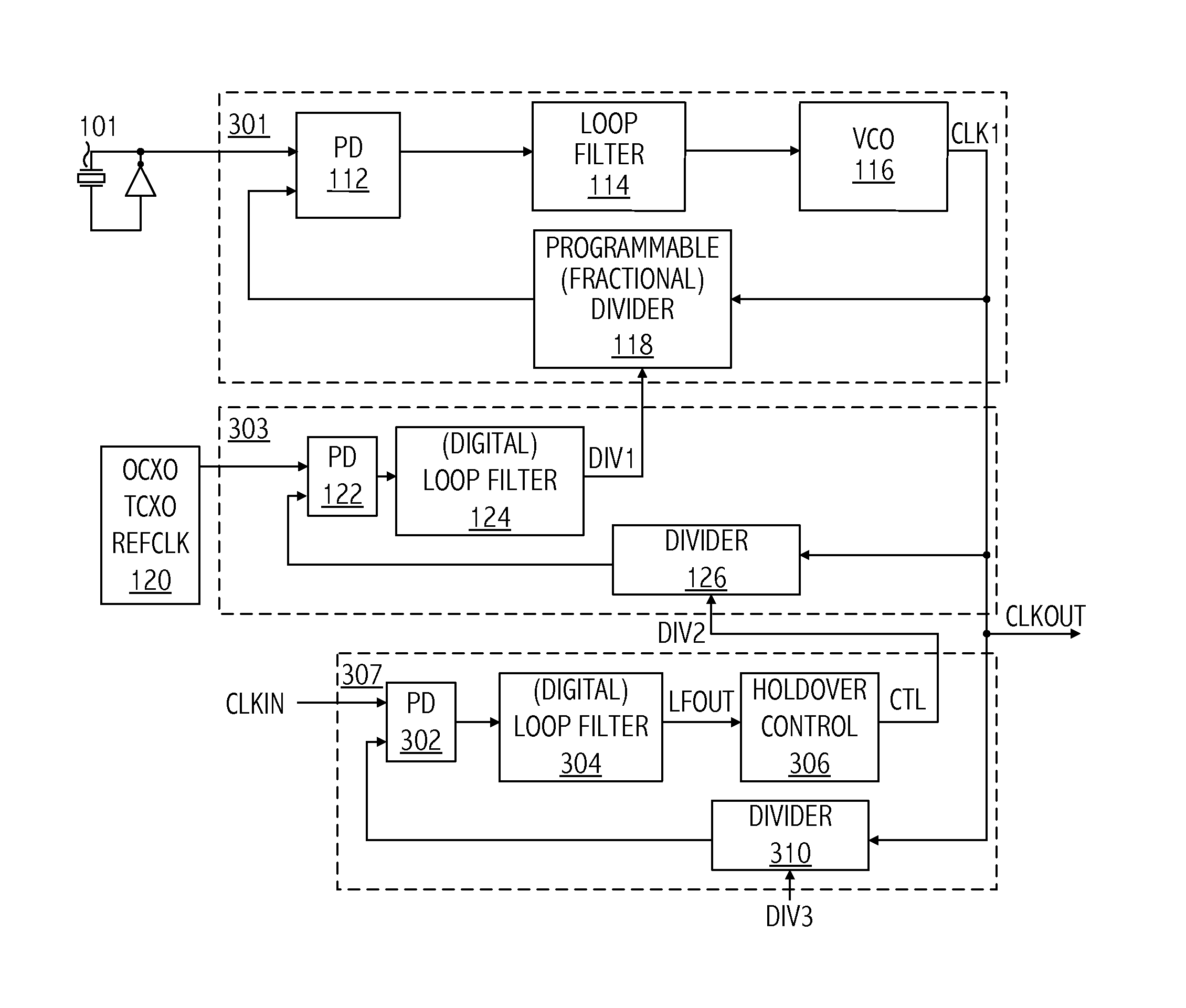
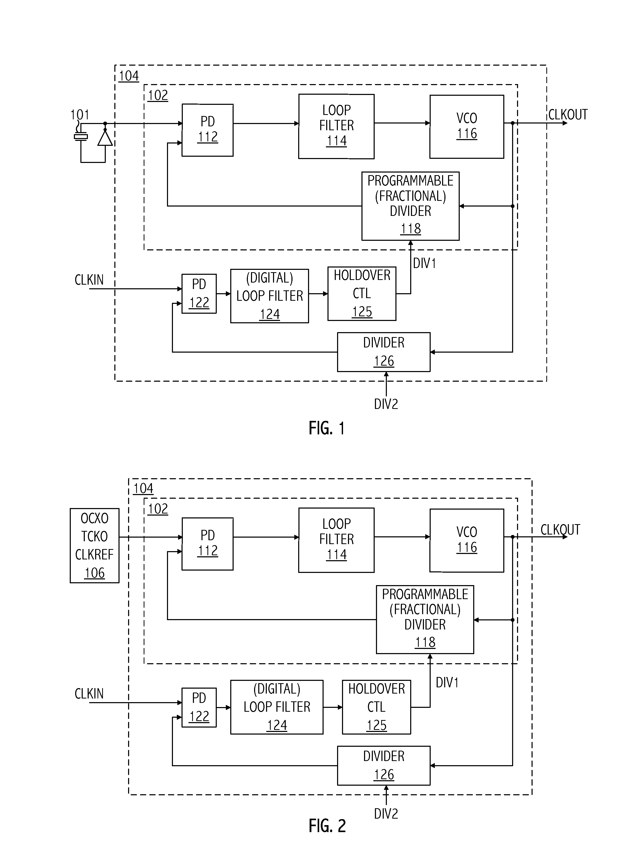
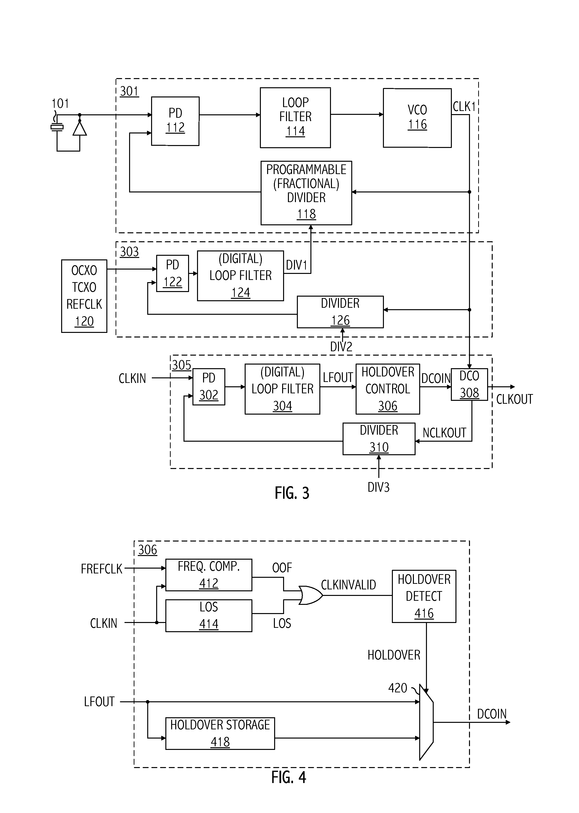
[0007]A cascaded phase-locked loop (PLL) clock generation technique reduces frequency drift of a low-jitter clock signal in a holdover mode. In at least one embodiment of the invention, an apparatus includes a first PLL circuit configured to generate a control signal based on a first clock signal and a first divider value. The apparatus includes a second PLL circuit configured to generate the first clock signal based on a low-jitter clock signal and a second divider value. The apparatus includes a third PLL circuit configured to generate the second divider value based on the first clock signal, a third divider value, and a second clock signal. The first PLL may generate an output clock signal based on the control signal and the first clock signal. The first PLL may provide the control signal to the third PLL circuit as the third divider value and may provide the first clock signal as an output clock signal. The low-jitter clock signal may have a greater temperature dependence than t...
PUM
 Abstract
Description
Claims
Application Information