
Sheet feeding apparatus and image forming apparatus

a technology of feeding apparatus and image forming apparatus, which is applied in the direction of transportation and packaging, thin material processing, and article separation, etc., can solve the problems of low operability, large burden of user, and large burden on the user, and achieves simple user operation and large capacity.

Inactive Publication Date: 2014-08-05
CANON KK
View PDF5 Cites 2 Cited by
  • Summary
  • Abstract
  • Description
  • Claims
  • Application Information

AI Technical Summary

Benefits of technology

[0011]The present invention is directed to enabling the release of stop or the detachment of a sheet storage unit with a large capacity by a simple user operation while the sheet storage unit is being drawn out.

Problems solved by technology

With the sheet feeding apparatus, the sheet storage unit that stores a large amount of sheets is greatly heavy.
Then, the user has to lift up the sheet storage unit and a burden of the user is greatly large.
However, as discussed in Japanese Patent Application Laid-Open No. 11-301861, the following problem occurs in a configuration to release an abutment state between the sheet storage unit and the stop member with the rotation thereof when detaching the sheet storage unit from the apparatus main body.
In the case where the sheet storage unit has a large capacity, the operability is low because a user must rotate the stop member while supporting the front side of the heavy sheet storage unit that stacks a large amount of sheets.
In addition, as discussed in US Patent Application Publication No. 2009 / 0057975, the following problem occurs in the configuration to draw out the sheet storage unit by obliquely lifting up the sheet storage unit to release the latch state with the latch member.
The operability is also low because it is required to draw out the sheet storage unit with a large capacity while the sheet storage unit is lifting up obliquely.
Therefore, if the sheet storage unit with the large capacity is heavy beyond user expectation, there is a danger that the sheet storage unit can carelessly fall and a setting surface can be thus damaged or the sheet storage unit can be damaged.

Method used


Image

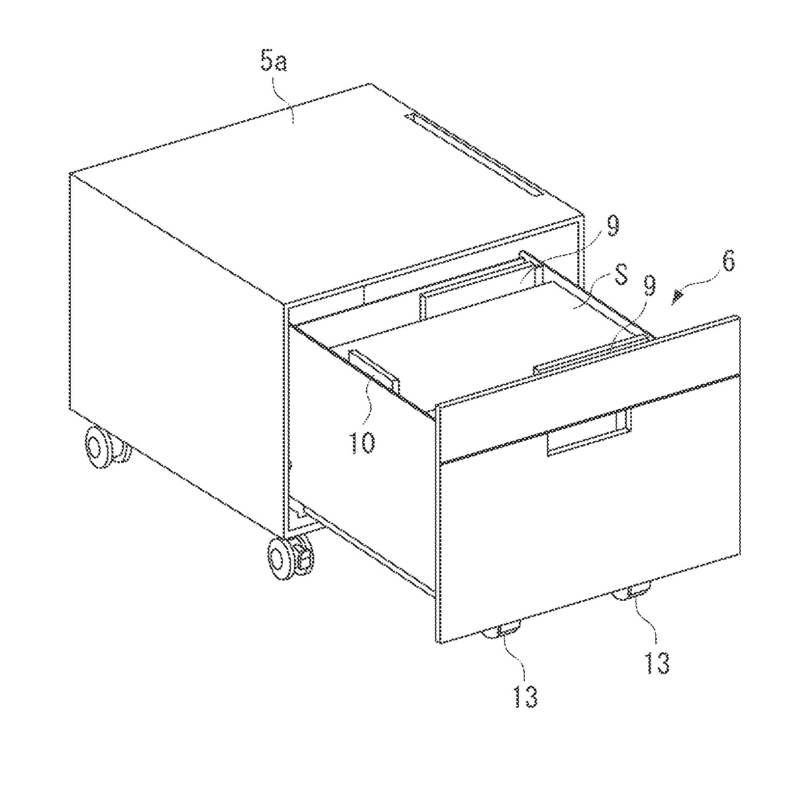
  • Sheet feeding apparatus and image forming apparatus
  • Sheet feeding apparatus and image forming apparatus
  • Sheet feeding apparatus and image forming apparatus

Examples


Embodiment Construction

[0021]Various exemplary embodiments, features, and aspects of the invention will be described in detail below with reference to the drawings.

[0022]A specific description is given of an exemplary embodiment of the present invention with reference to the drawings. It is possible to properly change the shape and relational arrangement of components in the exemplary embodiment depending on a configuration or conditions according to the present invention. The scope according to the present invention is not limited to the following exemplary embodiment.

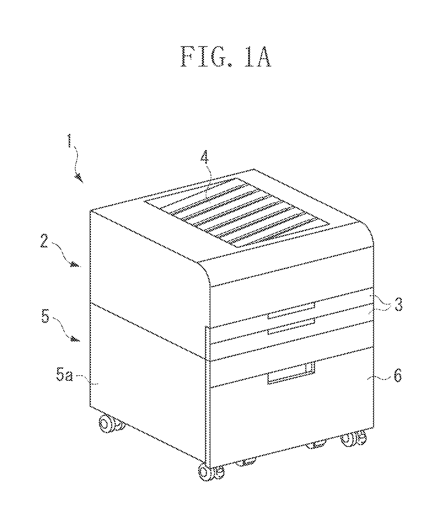
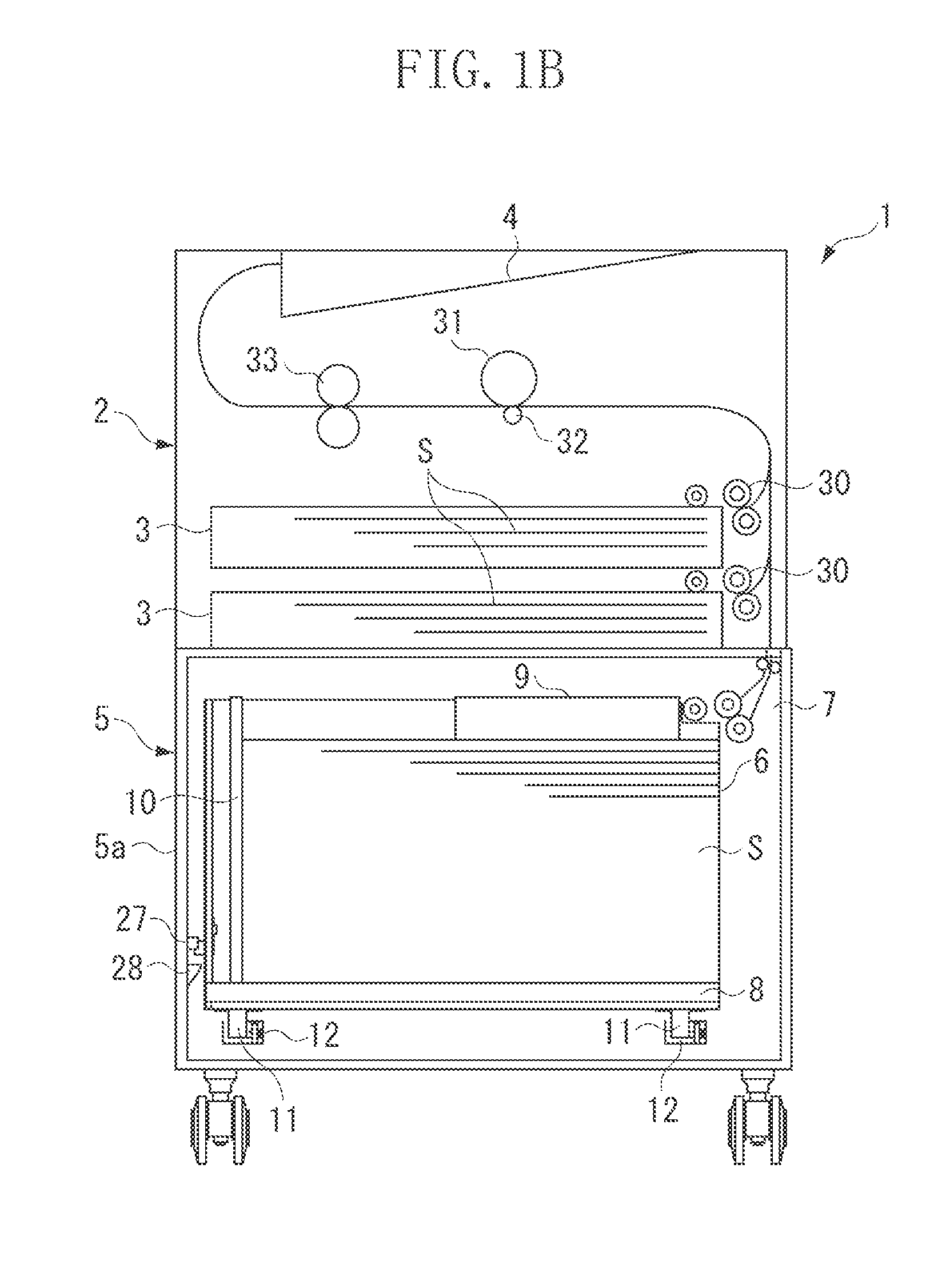
[0023]First of all, a description is given of a schematic configuration of an image forming apparatus to which a sheet feeding apparatus is attached according to the present invention with reference to FIGS. 1A and 1B. FIG. 1A illustrates an external perspective view of the image forming apparatus. FIG. 1B illustrates a longitudinal sectional view of the image forming apparatus.

[0024]An image forming apparatus 1 includes a sheet feeding app...


PUM


Abstract

The invention is directed to providing a sheet feeding apparatus including a stop mechanism configured to stop a sheet storage unit while the sheet storage unit is being drawn out from an apparatus main body, a stop release mechanism configured to release stop of the sheet storage unit by a stop mechanism and to enable detachment from the apparatus main body, a holding mechanism configured to hold a release state using the stop release mechanism of the stop of the sheet storage unit by the stop mechanism, and a return mechanism configured to release the holding of the release state of the stop mechanism by the holding mechanism while the sheet storage unit is being attached to the apparatus main body, and to return the sheet storage unit to a stop state using the stop mechanism.

Description

BACKGROUND OF THE INVENTION[0001]1. Field of the Invention[0002]The present invention relates to a sheet feeding apparatus that feeds a sheet to an image forming unit in an image forming apparatus and, in particular, to a drawing out mechanism of a sheet storage unit disposed in the sheet feeding apparatus.[0003]2. Description of the Related Art[0004]Conventionally, with a widespread image forming apparatus such as a copying machine, a printer, or a facsimile machine, sheets are fed one by one from a sheet feeding apparatus that stores sheets to an image forming unit and an image is formed thereon. With the sheet feeding apparatus, in general, the uppermost sheet is separated from the sheets stored in a sheet storage unit such as a sheet feeding cassette or a sheet feeding deck disposed in a main body of the sheet feeding apparatus. Then, the sheets are automatically fed one by one.[0005]Recently, for the image forming apparatus, a sheet feeding apparatus is increasingly demanded to...

Claims


Application Information

Patent Timeline
Patent Type & Authority Patents(United States)
IPC IPC(8): B65H1/00
CPCB65H1/266B65H2405/114B65H2405/121B65H2405/15B65H2601/26
Inventor YOSHIMURA, YURI
Owner CANON KK
Learn More