
Electrical connector having low profile characteristics

a technology of low-profile connectors and connectors, which is applied in the direction of fixed connections, coupling device connections, electric discharge lamps, etc., can solve the problems of clamshell type connectors occupying a relatively greater vertical space, and the separation between the base member and the cover shell, so as to ensure signal transmission stability and reliability, low profile characteristics

Inactive Publication Date: 2014-08-05
SANTA ELECTRONICS INC
View PDF4 Cites 2 Cited by
  • Summary
  • Abstract
  • Description
  • Claims
  • Application Information

AI Technical Summary

Benefits of technology

[0008]The present invention has been accomplished under the circumstances in view. It is therefore the main object of the present invention to provide an electrical connector, which has low profile characteristics and ensures signal transmission stability and reliability and provides fool-proof protection.
[0010]Further, the electrically insulative outer housing further comprises two sliding ways respectively longitudinally located on the side arms; the electrically insulative movable inner housing further comprises two slide blocks respectively located on the two upright sidewalls and respectively slidably coupled to the two sliding ways of the electrically insulative outer housing to guide sliding movement of the electrically insulative movable inner housing in and out of the electrically insulative outer housing smoothly and steadily facilitating accurate installation of an external RJ-45 modular plug of an external flexible connection interface. Subject to the slidable coupling arrangement between the electrically insulative outer housing and the electrically insulative movable inner housing, the electrical connector has low profile characteristics.

Problems solved by technology

However, when opening the cover shell, the pivot pins of the cover shell may be accidentally forced out of respective pivot holes at the base member, causing separation between the base member and the cover shell.
However, when the cover shell is opened and kept in the tilted open position, the clamshell type connector occupies a relatively greater vertical space.

Method used


Image

  • Electrical connector having low profile characteristics
  • Electrical connector having low profile characteristics
  • Electrical connector having low profile characteristics

Examples


Embodiment Construction

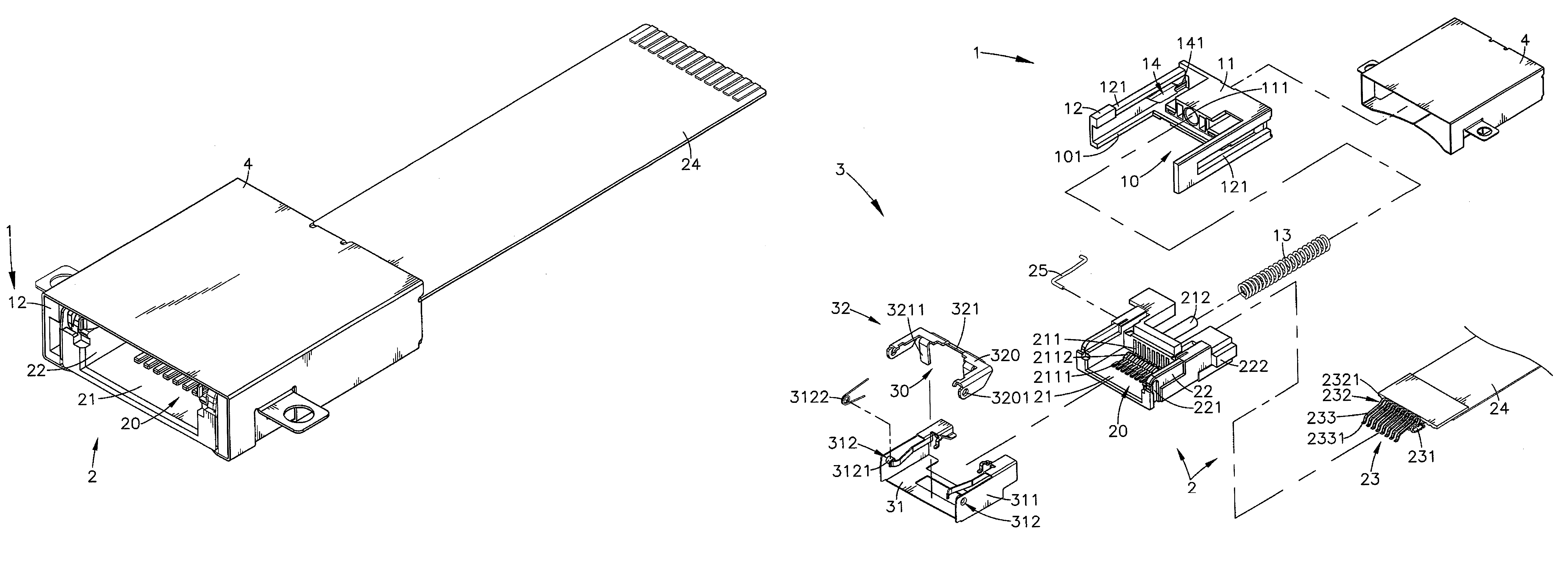
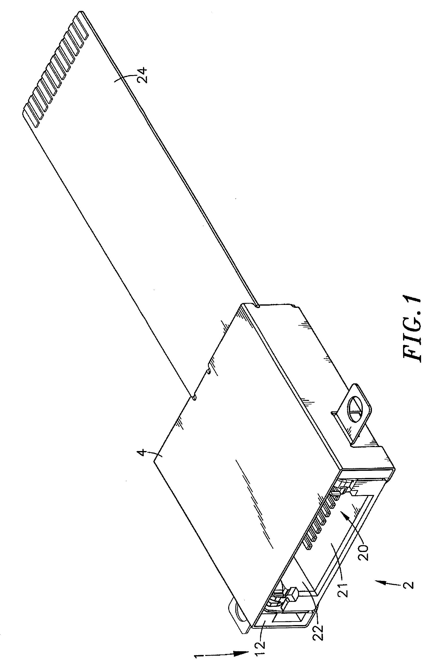
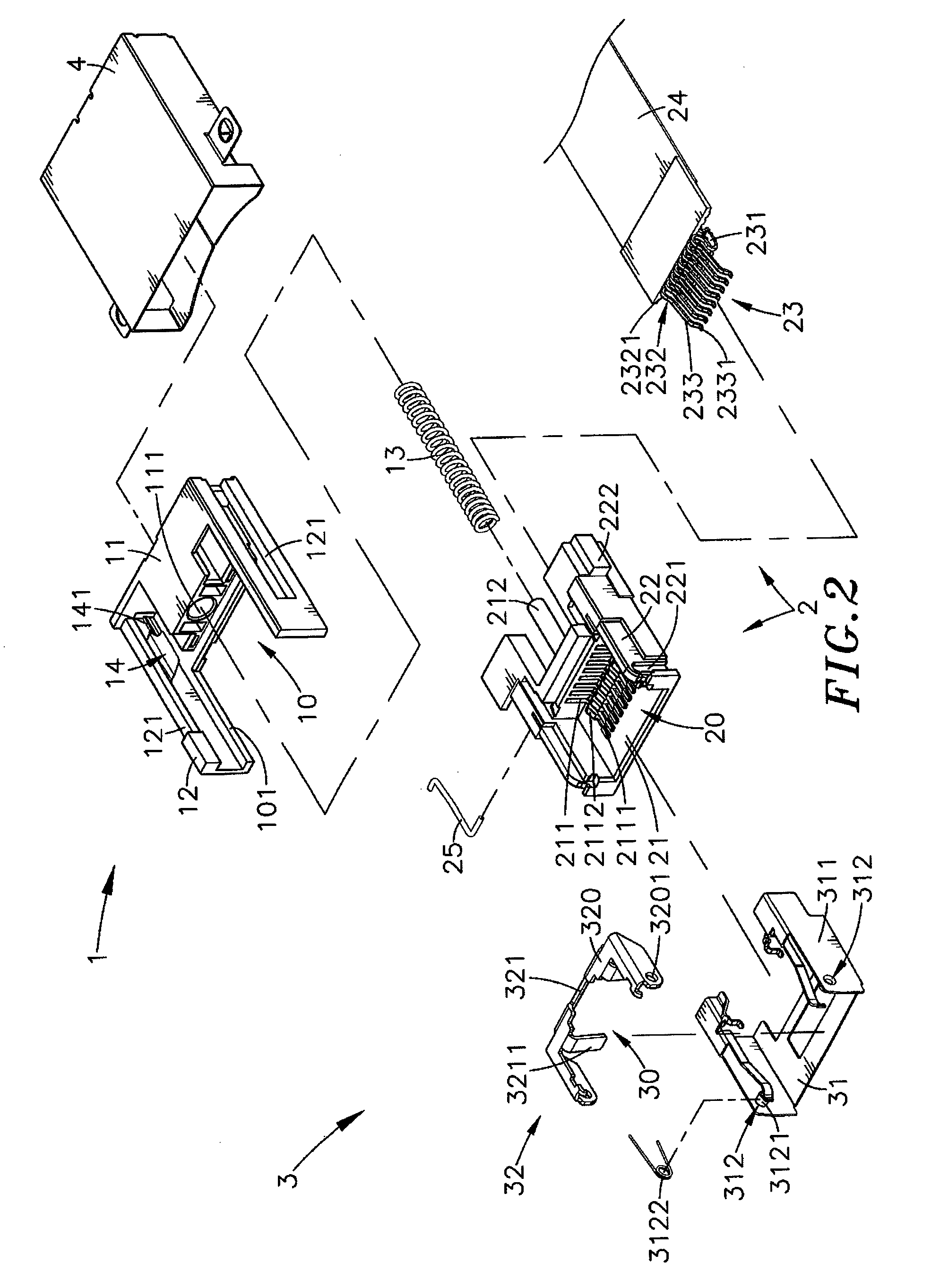
[0024]Referring to FIGS. 1, 2, 3 and 4, an electrical connector in accordance with the present invention is shown. The electrical connector comprises an electrically insulative outer housing 1, an electrically insulative movable inner housing 2, a set of mating contact pins 23, a flexible connection interface 24, a positioning mechanism 3, and a metal shield 4.

[0025]The outer housing 1 comprises a holder base 11, a recessed hole 111 located on the middle of the front side of the holder base 11, two side arms 12 extended from two opposite lateral sides of the holder base 11 in one same direction in a parallel manner, a sliding space 10 surrounded by the holder base 11 and the side arms 12 for accommodating the movable inner housing 2 and for enabling the movable inner housing 2 to be moved in and out of the outer housing 1, two sliding ways 121 respectively located on the side arms 12 and extending along the length of the side arms 12, and a bottom opening 101 at the bottom side of t...


PUM


Abstract

An electrical connector includes an outer housing having two side arms extended from two opposite lateral sides of a holder base thereof and defining with the holder base a sliding space, a movable inner housing movable in and out of the sliding space and having two upright sidewalls at two opposite lateral sides of a bottom panel thereof and defining with the bottom panel a mating space, mating contact pins mounted at the bottom panel of the movable inner housing and partially suspending in the mating space, and a flexible connection interface electrically connected with the mating contact pins and extending out of the movable inner housing and the outer housing for connection to an external transmission interface.

Description

[0001]This application claims the priority benefit of Taiwan patent application number 100139143, filed on Oct. 27, 2011.BACKGROUND OF THE INVENTION[0002]1. Field of the Invention[0003]The present invention relates to electrical connector technology and more particularly, to a low-profile electrical connector, which comprises an outer housing, a movable inner housing movable in and out of a sliding space of the outer housing, mating contact pins mounted inside the movable inner housing, and a flexible connection interface electrically connected with the mating contact pins and extending out of the movable inner housing and the outer housing for connection to an external transmission interface.[0004]2. Description of the Related Art[0005]Following fast development of computer technology, notebook computers, tablet computers and many other high mobility electronic apparatus are well developed and widely used by people for different applications. Further, with the fast and vigorous dev...

Claims


Application Information

Patent Timeline
Patent Type & Authority Patents(United States)
IPC IPC(8): H01R13/44
CPCH01R12/62H01R13/6275H01R24/64H01R2201/06
Inventor LIU, HSIEN-CHUN
Owner SANTA ELECTRONICS INC
Learn More