Lens assembly with an image sensor backoff mechanism

a technology of lens assembly and image sensor, which is applied in the field of camera lens assembly, can solve the problems of inconvenient fabrication or assembly, inability to make thinner cameras of this design, and complicated structure of lens assembly, etc., and achieves the effects of simple structure, reduced thickness, and convenient fabrication and assembly

Active Publication Date: 2014-05-06
ASIA OPTICAL INT LTD
View PDF11 Cites 0 Cited by
  • Summary
  • Abstract
  • Description
  • Claims
  • Application Information

AI Technical Summary

Benefits of technology

[0006]The present invention has been accomplished under the circumstances in view. It is the main object of the present invention to provide a lens assembly, which enables the camera to reduce the thickness. It is another object of the present invention to provide a lens assembly, which has a simple structure and is easy to make and to assemble.
[0008]The lens assembly is mounted inside the camera housing by means of the base frame. When retracting the lens assembly, the lens barrel is moved from the first position to the second position, and at the same time, the image sensor is moved to the non-operative backoff position. Thus, the lens can be carried by the lens barrel to the operative position of the image sensor or over the operative position of the image sensor to a position relatively closer to the base frame when the lens assembly is retracted. Thus, the thickness of the lens assembly can be greatly reduced when it is retracted. Thus, a camera using this design of lens assembly has a low profile characteristic. Further, because the lens and the image sensor are movable straightly back and forth, the lens assembly has a simple structure, facilitating fabrication and assembly.

Problems solved by technology

In consequence, a camera of this design cannot be made thinner.
However, as the lens sets must be moved axially and radially during retraction of the lens assembly, the structure of the lens assembly is complicated, not convenient to fabricate or to assemble.

Method used


Image

  • Lens assembly with an image sensor backoff mechanism
  • Lens assembly with an image sensor backoff mechanism
  • Lens assembly with an image sensor backoff mechanism

Examples


first embodiment

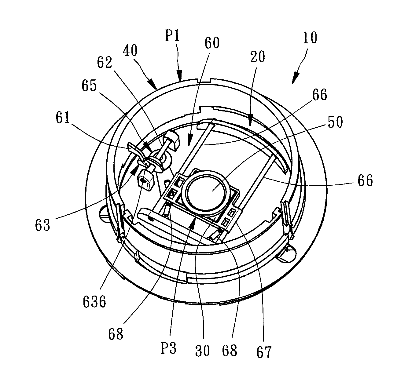
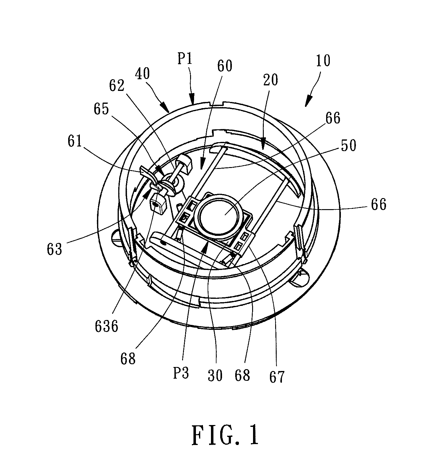
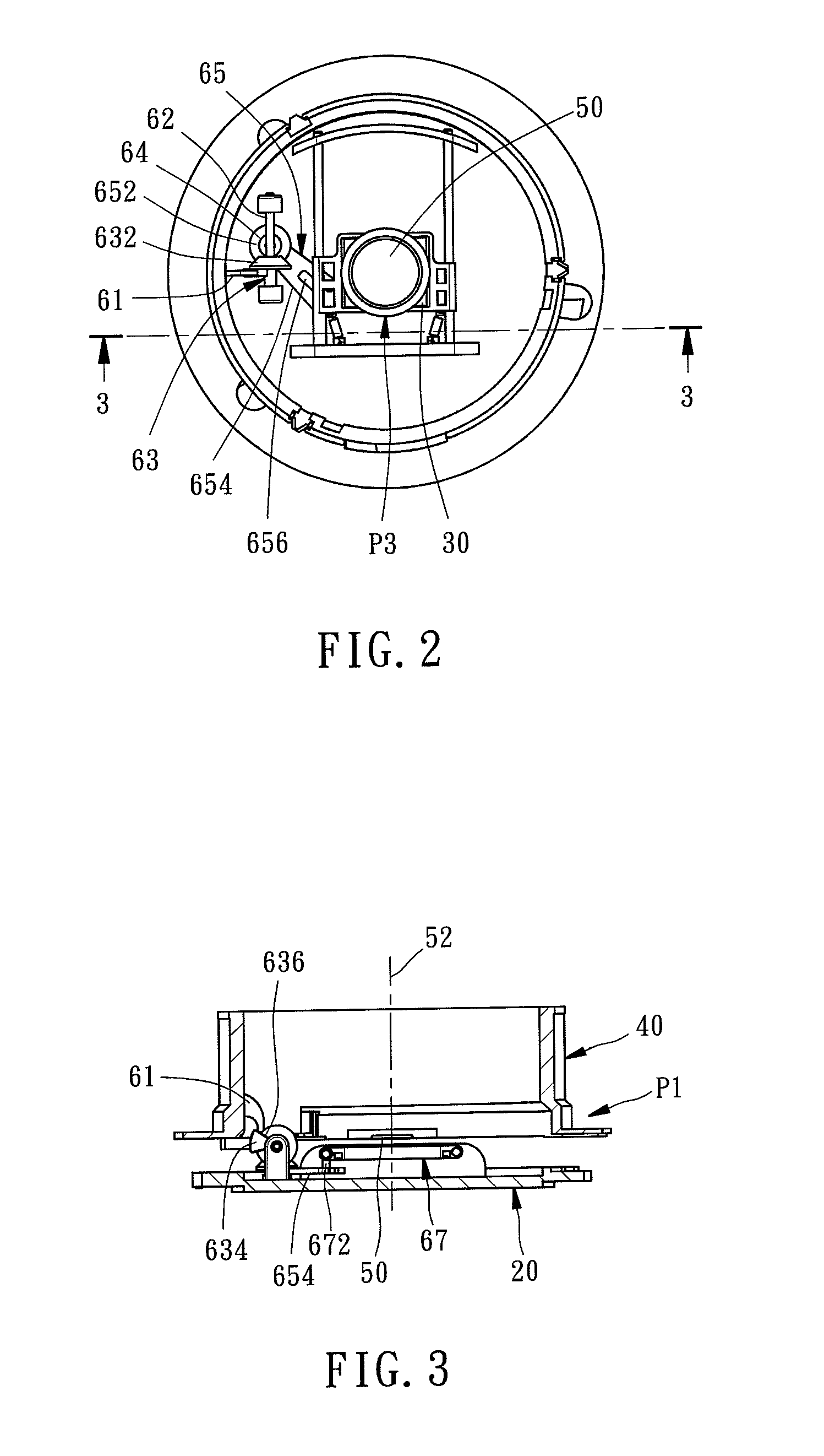
[0018]Referring to FIGS. 1-3, a lens assembly 10 in accordance with the present invention is shown comprising a base frame 20, an image sensor 30, a lens barrel 40, a lens 50 and a backoff mechanism 60.

[0019]The base frame 20 is adapted for mounting in a camera housing (not shown). The image sensor 30 is mounted at the base frame 20 by means of the backoff mechanism 60. The lens 50 is mounted in the lens barrel 40. The lens barrel 40 is moved to a first position P1 far from the base frame 20 (see FIGS. 1-3) when the camera initiates the lens assembly 10. When the camera shuts off the lens assembly 10, the lens barrel 40 is moved from the first position P1 to a second position P2 close to the base frame 20 (see FIGS. 4-6), carrying the lens 50 along an optical axis 52 toward the base frame 20.

[0020]The lens barrel 40 may be designed to hold more lenses, lens fixtures and other optical components. Further, as the arrangement and movement of the lens barrel 40 are of the known art, no ...

second embodiment

[0030]FIGS. 7 and 8 illustrate a lens assembly 70 in accordance with the present invention to explain the image sensor 30 movement by means of the backoff mechanism 60.

[0031]In the lens assembly 70 of this second embodiment, a rotating barrel 74 is mounted on the base frame, referenced by 71, to move two lens barrels 75 and 76 toward or away from the base frame 71. Further, each lens barrel 75 or 76 holds a respective lens set 77 or 78. The bump 61 of the backoff mechanism 60 in this second embodiment is connected to the bottom side of the lens barrel 76. When the camera shuts off the lens assembly 70, the lens barrel 76 is moved from the first position P1 shown in FIG. 7 to a second position P2 shown in FIG. 8, and at the same time, the image sensor 30 is moved away from the operative position P3 by the backoff mechanism 60. Thus, one lens 782 of the lens set 78 is moved to the operative position P3 of the image sensor 30, reducing the thickness of the retracted condition of the le...


PUM


Abstract

A lens assembly includes a base frame, an image sensor, a lens barrel, a lens and a backoff mechanism. By means of the backoff mechanism, the image sensor is mounted at the base frame and movable between an operative position and a non-operative backoff position. When the image sensor is in the operative position, the lens barrel is in a first position far frame the base frame, and the optical axis of the lens intersects the image sensor. When the lens barrel is moved to a second position close to the base frame, the image sensor is moved to the non-operative backoff position, and the optical axis of the lens is not intersected with the image sensor.

Description

BACKGROUND OF THE INVENTION[0001]1. Field of the Invention[0002]The present invention relates to camera lens technology and more particularly, to a lens assembly for camera, which uses a backoff mechanism to move the image sensor away from the optical axis of the lens when the lens is retracted, so that the thickness of the retracted condition of the lens assembly can be minimized.[0003]2. Description of the Related Art[0004]The lens assemblies of regular cameras commonly adopt a retractable design. Thus, the lens barrel that holds a set of lenses can be extended out of the camera housing when taking a picture, or received inside the camera housing when not to take pictures. When retracting the lens assembly, the lenses and optical components in the lens barrel are moved straightly along the optical axis of the lenses toward the image sensor (such as charge coupled device, or CCD) in the camera housing. After retraction, the lenses, the optical components and the image sensor are st...

Claims


Application Information

Patent Timeline
Patent Type & Authority Patents(United States)
IPC IPC(8): G03B17/04H04N5/225
CPCG03B2205/0092G03B17/04H04N5/2253G03B2205/00H04N23/54
Inventor HWANG, DUEN-KWEICHEN, KAI-KUN
Owner ASIA OPTICAL INT LTD
Why Eureka
Try Eureka