Lens assembly with an image sensor backoff mechanism
a technology of image sensor and lens assembly, which is applied in the field of lens assembly for cameras, can solve the problems of inconvenient fabrication or assembly, inability to make thinner cameras of this design, and complicated structure of lens assembly, etc., and achieves the effects of simple structure, reduced thickness, and convenient fabrication and assembly
- Summary
- Abstract
- Description
- Claims
- Application Information
AI Technical Summary
Benefits of technology
Problems solved by technology
Method used
Image
Examples
first embodiment
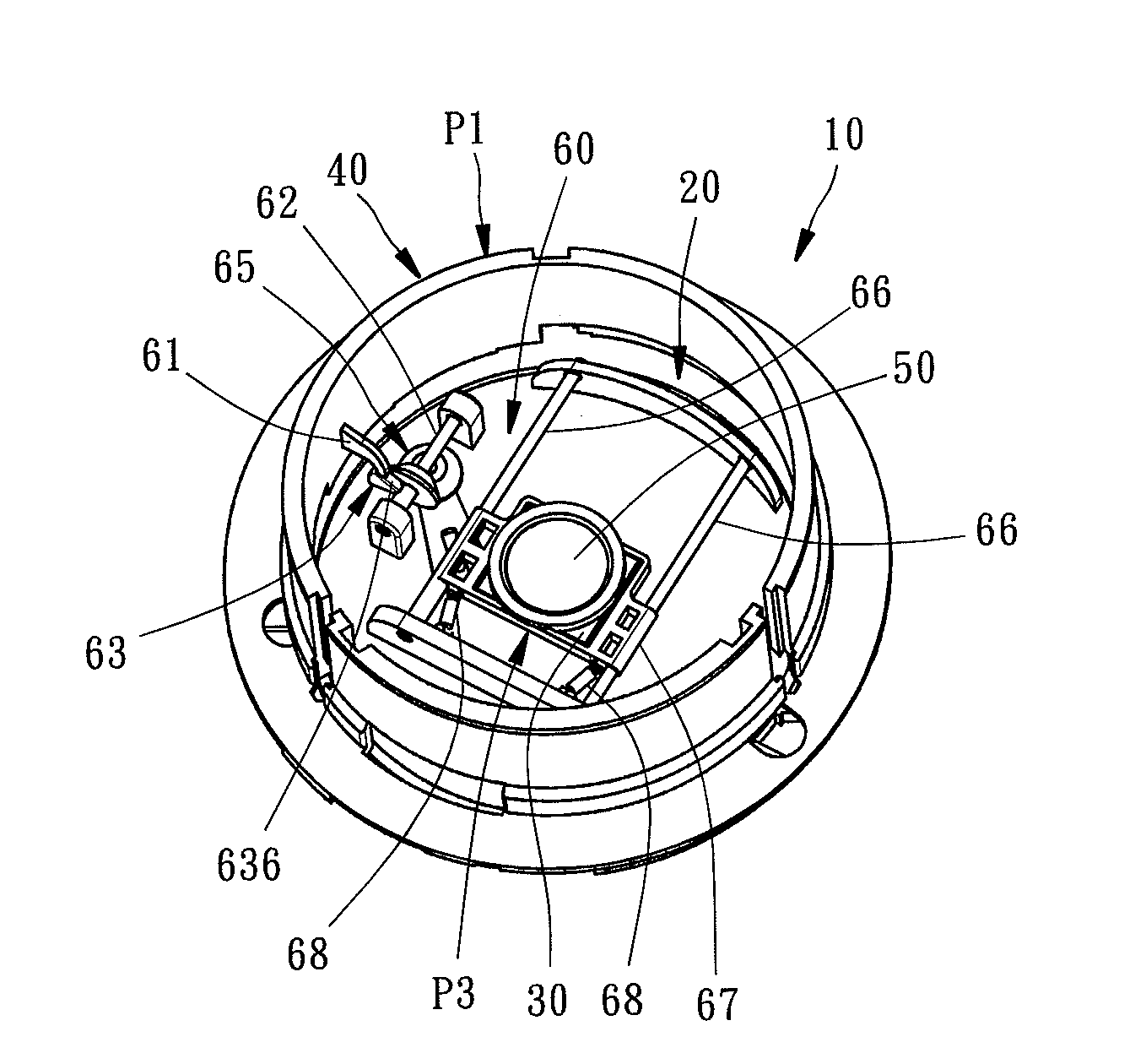
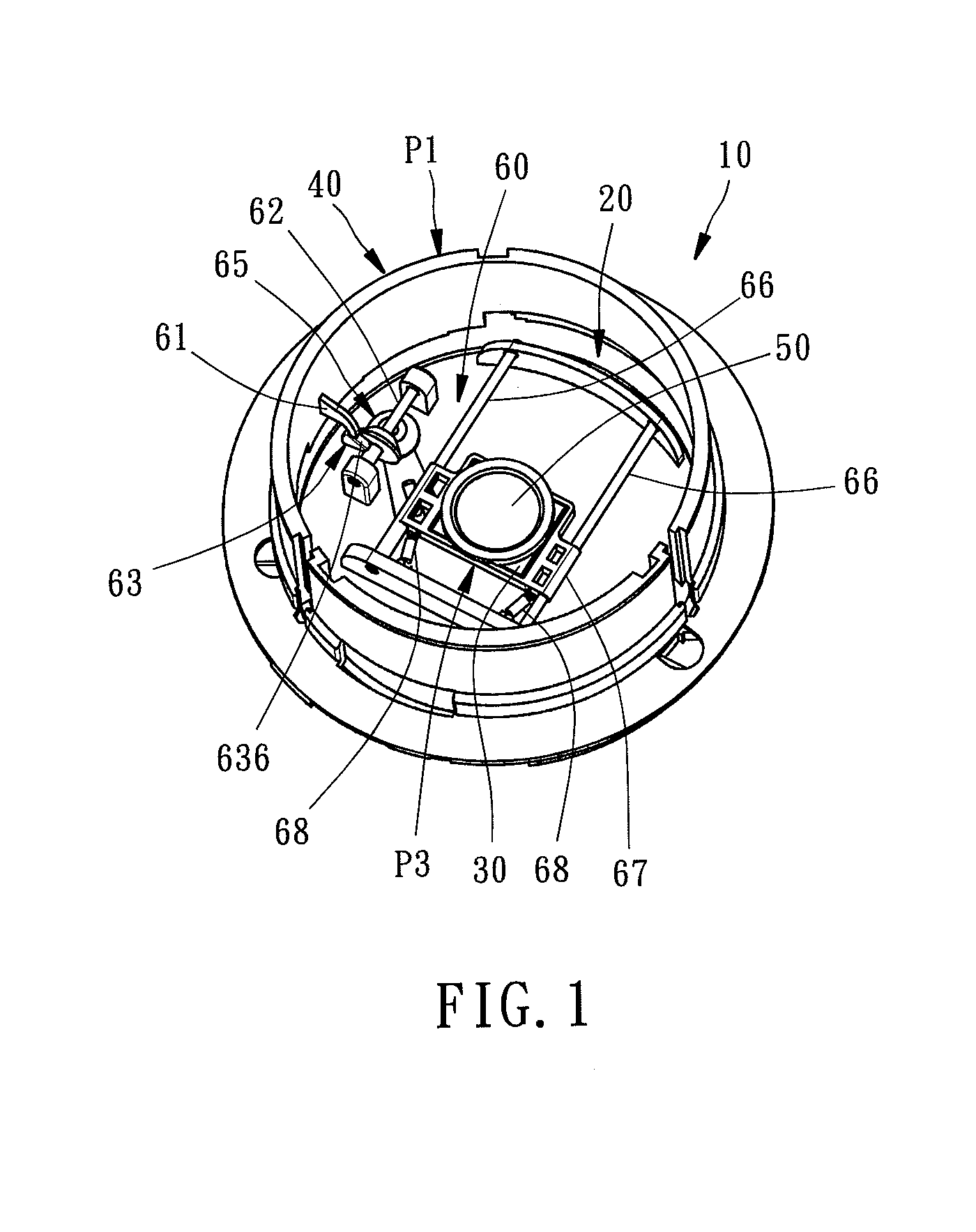
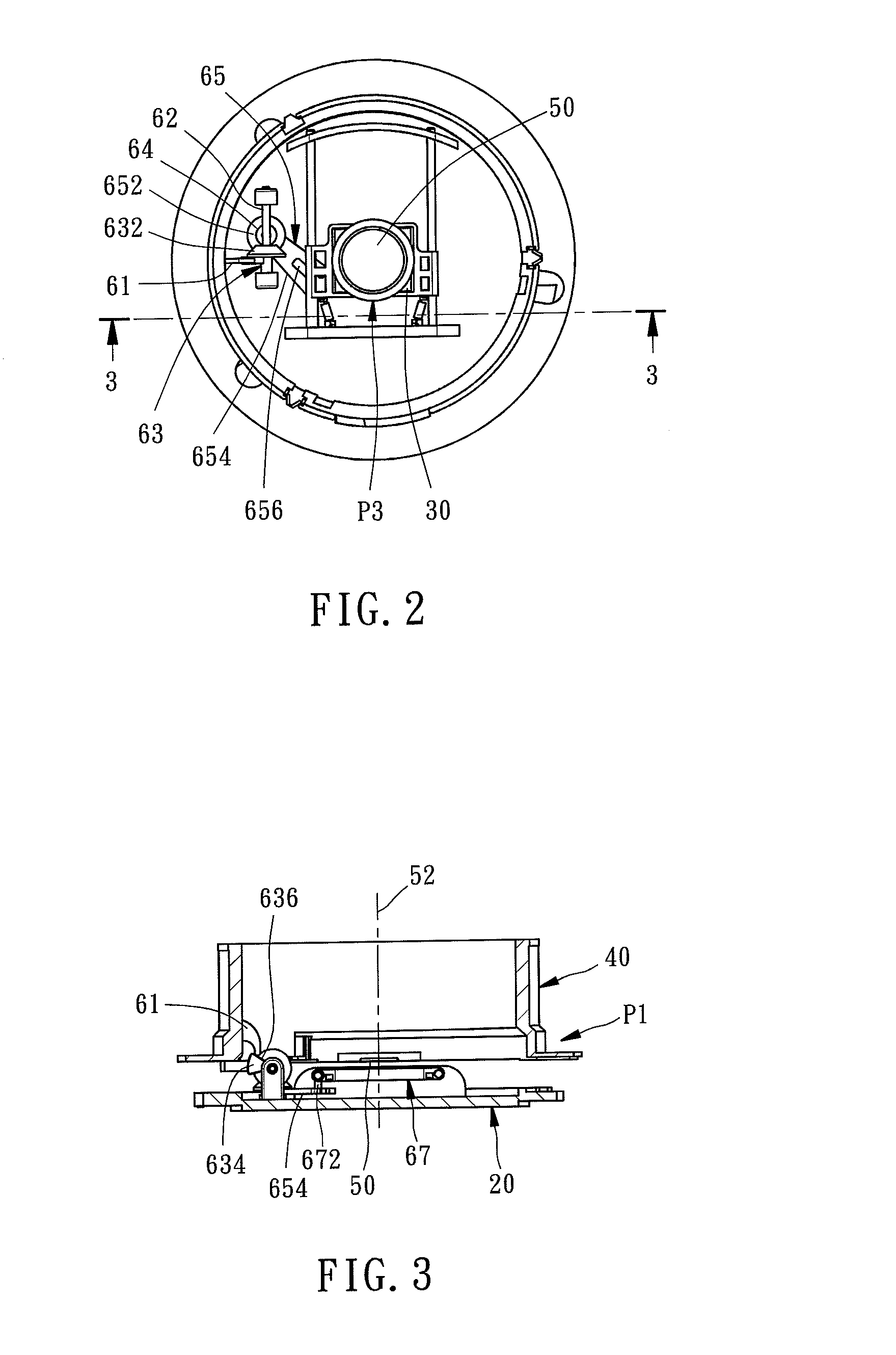
[0018]Referring to FIGS. 1-3, a lens assembly 10 in accordance with the present invention is shown comprising a base frame 20, an image sensor 30, a lens barrel 40, a lens 50 and a backoff mechanism 60.
[0019]The base frame 20 is adapted for mounting in a camera housing (not shown). The image sensor 30 is mounted at the base frame 20 by means of the backoff mechanism 60. The lens 50 is mounted in the lens barrel 40. The lens barrel 40 is moved to a first position P1 far from the base frame 20 (see FIGS. 1-3) when the camera initiates the lens assembly 10. When the camera shuts off the lens assembly 10, the lens barrel 40 is moved from the first position P1 to a second position P2 close to the base frame 20 (see FIGS. 4-6), carrying the lens 50 along an optical axis 52 toward the base frame 20.
[0020]The lens barrel 40 may be designed to hold more lenses, lens fixtures and other optical components. Further, as the arrangement and movement of the lens barrel 40 are of the known art, no ...
second embodiment
[0030]FIGS. 7 and 8 illustrate a lens assembly 70 in accordance with the present invention to explain the image sensor 30 movement by means of the backoff mechanism 60.
[0031]In the lens assembly 70 of this second embodiment, a rotating barrel 74 is mounted on the base frame, referenced by 71, to move two lens barrels 75 and 76 toward or away from the base frame 71. Further, each lens barrel 75 or 76 holds a respective lens set 77 or 78. The bump 61 of the backoff mechanism 60 in this second embodiment is connected to the bottom side of the lens barrel 76. When the camera shuts off the lens assembly 70, the lens barrel 76 is moved from the first position P1 shown in FIG. 7 to a second position P2 shown in FIG. 8, and at the same time, the image sensor 30 is moved away from the operative position P3 by the backoff mechanism 60. Thus, one lens 782 of the lens set 78 is moved to the operative position P3 of the image sensor 30, reducing the thickness of the retracted condition of the le...
PUM
 Abstract
Description
Claims
Application Information
 - R&D
- Intellectual Property
- Life Sciences
- Materials
- Tech Scout
- Unparalleled Data Quality
- Higher Quality Content
- 60% Fewer Hallucinations
Browse by: Latest US Patents, China's latest patents, Technical Efficacy Thesaurus, Application Domain, Technology Topic, Popular Technical Reports.
© 2025 PatSnap. All rights reserved.Legal|Privacy policy|Modern Slavery Act Transparency Statement|Sitemap|About US| Contact US: help@patsnap.com


