
Discharge ionization current detector

a technology of ionization current and detector, which is applied in the field of ionization current detector, can solve the problems of low ionization efficiency, low ionization efficiency of alcohol, aromatic substances, chlorine substances, etc., and achieve the effect of higher s/n ratio

Active Publication Date: 2014-08-05
SHIMADZU CORP +1
View PDF7 Cites 3 Cited by
  • Summary
  • Abstract
  • Description
  • Claims
  • Application Information

AI Technical Summary

Benefits of technology

[0007]The present invention has been made to solve the previously described problems, and a purpose thereof is to provide a discharge ionization current detector capable of diminishing an influence of a disturbance noise caused by a sudden-appearance of an electromagnetic noise or thereto-electromotive force due to a temperature-difference as much as possible so as to obtain an ionization current signal originating from a component to be detected at high sensitivity and accuracy.
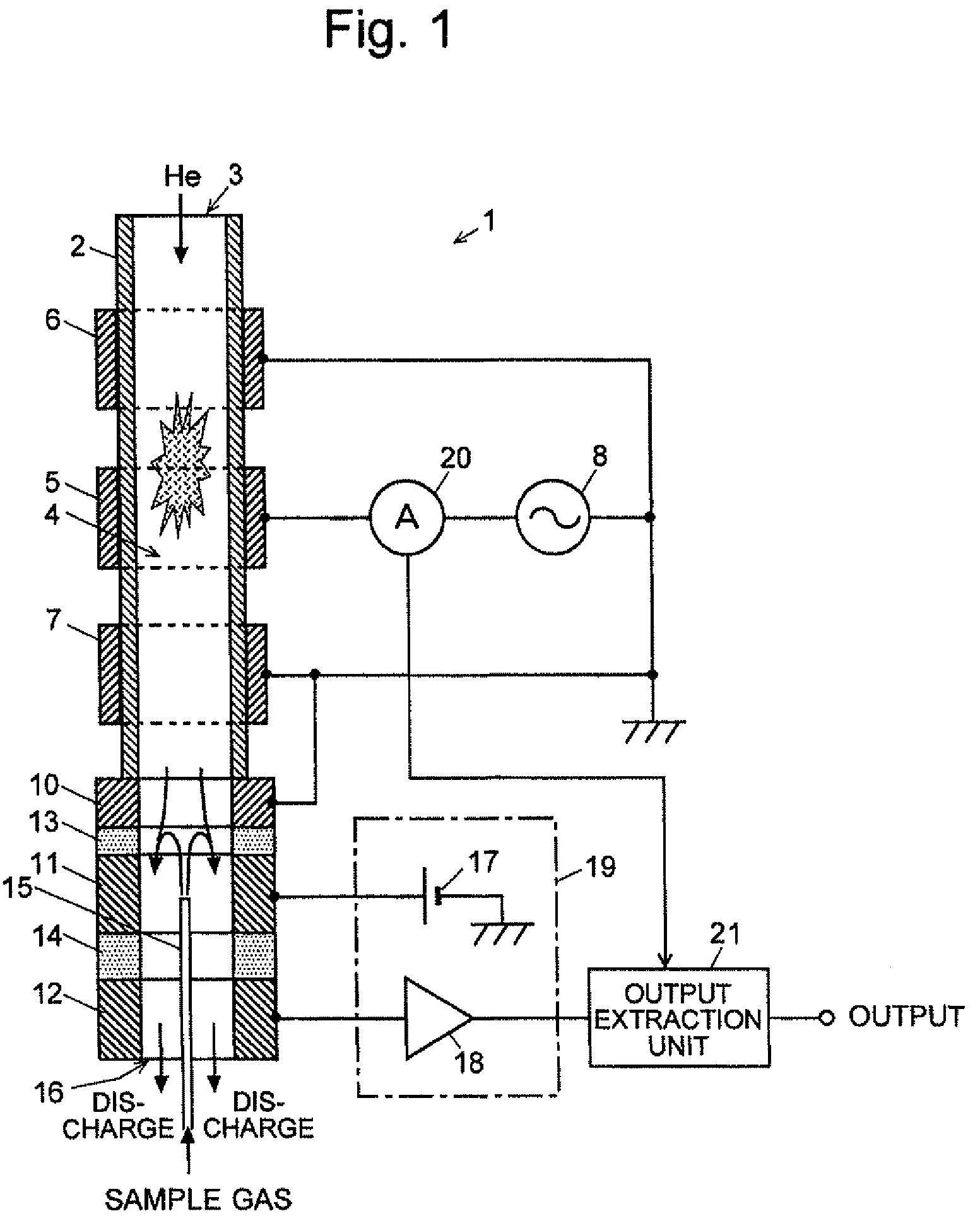
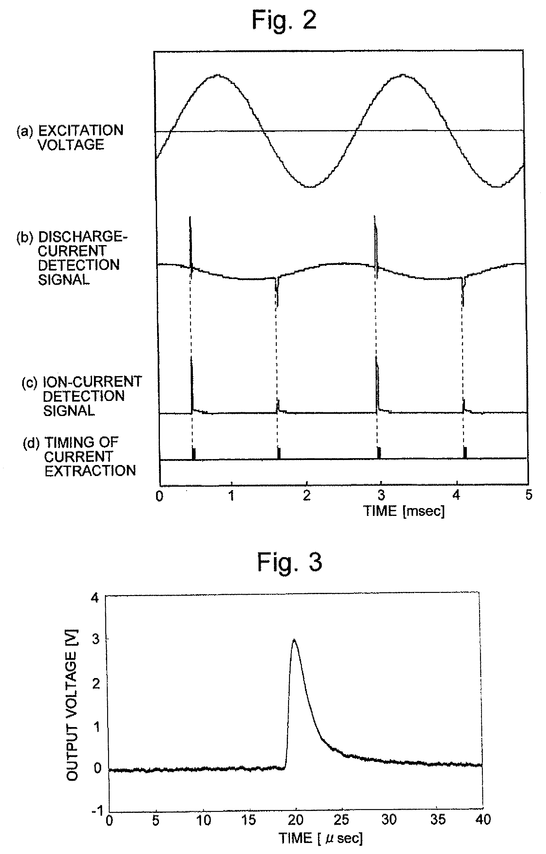
[0017]As one embodiment of the present invention, the emission timing detection means may serve as a current detection means for detecting a current supplied from the voltage application means to the electrodes. Although the low-frequency AC voltage is continuously applied to the electrodes from the voltage application means, the discharge current flows only when the electric discharge actually occurs to cause the plasma emission. Accordingly, the timing of the flow of the discharge current is synchronized with the plasma emission, so that the current detection means can indirectly detect the timing of the plasma emission.
[0021]According to the discharge ionization current detector of the present invention, a disturbance noise contained in a signal extracted as a detection output can be reduced, thereby improving the S / N ratio of the signal. As a result, the detection sensitivity or detection accuracy of the sample component can be enhanced.
[0023]Accordingly, in the discharge ionization current detector according to the present invention, the signal extraction means preferably acquires a signal corresponding to an ion current detected by the current detection means at a timing synchronized with the plasma emission during a time period in which a positive voltage is applied to the high-voltage electrode between the pair of electrodes included in the discharge generation means based on the detection result by the emission timing detection means. This configuration enables the extraction of the detection signal having a further higher S / N ratio.

Problems solved by technology

However, the FID has the following drawbacks: (1) Its ionization efficiency is low, so that its minimum detectable amount is not sufficiently low.
(2) Its ionization efficiency for alcohols, aromatic substances, and chlorine substances is low.
(3) It requires hydrogen, which is a highly hazardous substance; therefore, an explosion-proof apparatus or similar kind of special equipment must be provided, which makes the entire system more difficult to operate.
However, it is practically impossible to completely prevent the invasion of a noise from certain parts of the device, such as an opening for introducing and / or discharging a sample gas or a carrier gas.
Therefore, it is very difficult to completely suppress the influence of the thermo-electromotive force occurring between the heated detector cell and a circuit at room temperature.

Method used


Image

  • Discharge ionization current detector
  • Discharge ionization current detector
  • Discharge ionization current detector

Examples


Embodiment Construction

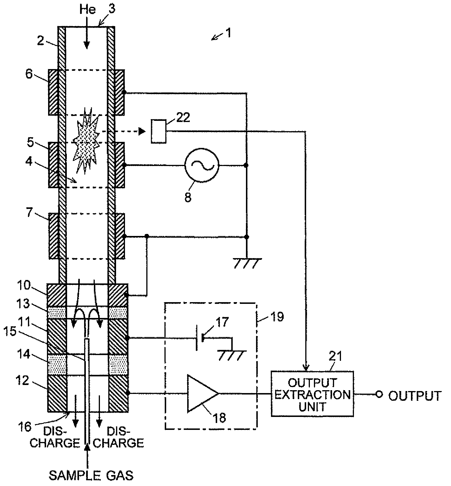
[0028]A discharge ionization current detector according to an embodiment of the present invention is hereinafter described with reference to the attached drawings. FIG. 1 is a schematic configuration diagram of the discharge ionization current detector according to the present embodiment.

[0029]A discharge ionization current detector 1 of the present embodiment includes a cylindrical tube 2 made of a dielectric material, such as quartz. The inner space of this tube 2 is a gas passage 4. For example, the cylindrical tube 2 may be a quartz tube having an outer diameter of 3.9 mm. Ring-shaped plasma generation electrodes 5, 6, and 7, which are made of a metal (e.g. stainless steel or copper), are circumferentially provided at predetermined intervals on the outer wall surface of the cylindrical tube 2. According to this design, the dielectric wall of the cylindrical tube 2 between the gas passage 4 and the plasma generation electrodes 5, 6 and 7 functions as a dielectric coating layer th...


PUM

PropertyMeasurementUnit
frequencyaaaaaaaaaa
frequencyaaaaaaaaaa
outer diameteraaaaaaaaaa

Abstract

A discharge ionization current detector using a low-frequency dielectric barrier discharge with an improved S / N ratio is provided. A current detector 20 is disposed between an excitation high-voltage power source 8 and a discharge electrode 5 to detect a discharge current flowing in pulses due to plasma generation. The detection signal of the current detector 20 and an output signal from a current amplifier 18 for amplifying an ion current are inputted into an output extraction unit 21. The output extraction unit 21 detects a precipitous-rise portion of the discharge current detection signal and generates a trigger signal, and then extracts an ion current signal for a predetermined time period from the trigger signal. This can remove an influence of a noise appearing in a signal during a time period where no plasma emission is generated, thereby improving the S / N ratio of the detection signal.

Description

[0001]The present invention relates to a discharge ionization current detector primarily suitable as a detector for a gas chromatograph (GC), and more specifically to a discharge ionization current detector using a low-frequency barrier discharge.BACKGROUND OF THE INVENTION[0002]As a detector for a gas chromatograph, various types of detectors have been practically applied, such as a thermal conductivity detector (TCD), electron capture detector (ECD), flame ionization detector (FID), flame photometric detector (FPD), and flame thermionic detector (FTD). Among these detectors, the FID is most widely used, particularly for the purpose of detecting organic substances. The FID is a device that ionizes sample components in a sample gas by hydrogen flame and detects the resultant ion current. It can attain a wide dynamic range of approximately six orders of magnitude. However, the FID has the following drawbacks: (1) Its ionization efficiency is low, so that its minimum detectable amount...

Claims


Application Information

Patent Timeline
Patent Type & Authority Patents(United States)
IPC IPC(8): G01N27/62G01N27/68G01N27/70
CPCG01N27/70G01N27/68G01N27/62G01N30/64
Inventor SHINADA, KEIHORIIKE, SHIGEYOSHINISHIMOTO, TAKAHIROKITANO, KATSUHISA
Owner SHIMADZU CORP
Learn More