System for providing lung ventilation information

a technology for providing lung ventilation and information, applied in the field of systems for displaying lung ventilation information, to achieve the effect of improving the assessment of local lung ventilation

Active Publication Date: 2014-08-05
KONINKLIJKE PHILIPS ELECTRONICS NV
View PDF22 Cites 23 Cited by
  • Summary
  • Abstract
  • Description
  • Claims
  • Application Information

AI Technical Summary

Benefits of technology

[0011]By computing the local ventilation, for each phase transition the degree of contraction or expansion can be delivered to the physician. The amount of ventilation can be delivered for any user-chosen position in the lung and for any moment during a breathing cycle, rather than as a global amount for a complete breathing cycle. This system makes it possible to display relevant information in all spatial dimensions (2D or 3D) and simultaneously display information in a temporal dimension. The displayed ventilation images show a lung ventilation distribution for the imaged region, while the diagram or diagrams show the time course of the local ventilation at one or more specific positions or regions. The positions or regions may be selected automatically or by user interaction. For example, a tumor region or a reference region with healthy tissue may be selected. With the system according to the invention, not only a comparison of max-inhale and max-exhale state can be performed, but any two phases can be compared, yielding a temporal measurement of local lung ventilation. It is to be noted that even if the ventilation computed for the transition from maximum inhalation to maximum exhalation is the same at two different positions or for two patients, the phase-to-phase ventilation may be different. The information from all phase-to-phase ventilation images provides a better tool for early cancer diagnosis. In an embodiment of the system according to the invention, a respiratory cycle model is fitted to the generated function. The fitted model may be displayed together with the generated function in order to visualize the differences between the theoretical model and the measured ventilation profile. Moreover, the parameters used for fitting the respiratory cycle model to the generated function may hold useful information such as ventilation amplitude or ventilation phase shift. If such parameters are determined for different positions in the lung, they may be visualized in a lung atlas showing the parameter values at corresponding positions, e.g. using color coding.

Problems solved by technology

It is a problem of the system of JP 2005-028121 that the output picture only provides information about the local volume change for a complete breathing cycle.

Method used


Image

  • System for providing lung ventilation information
  • System for providing lung ventilation information
  • System for providing lung ventilation information

Examples


Embodiment Construction

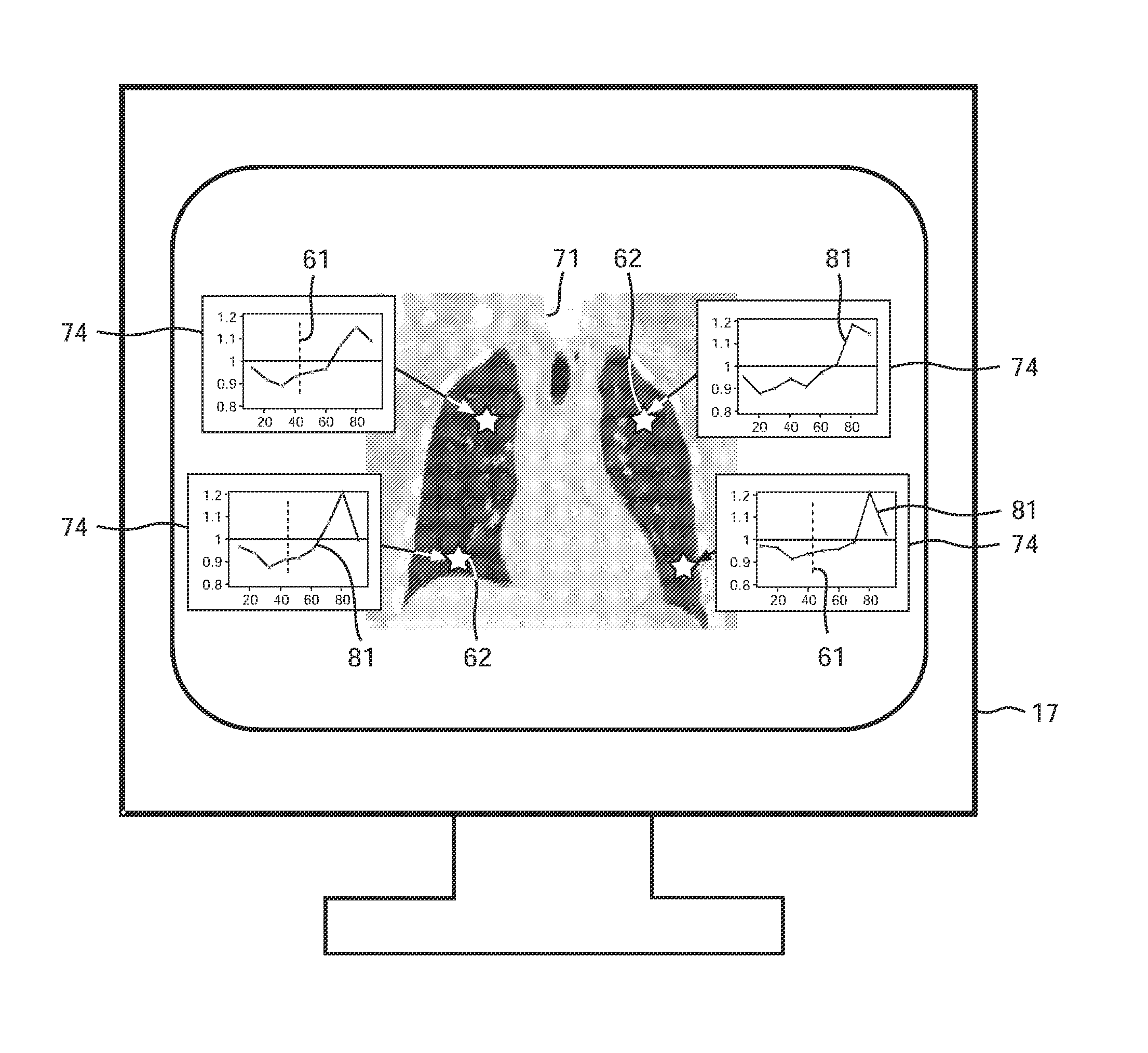
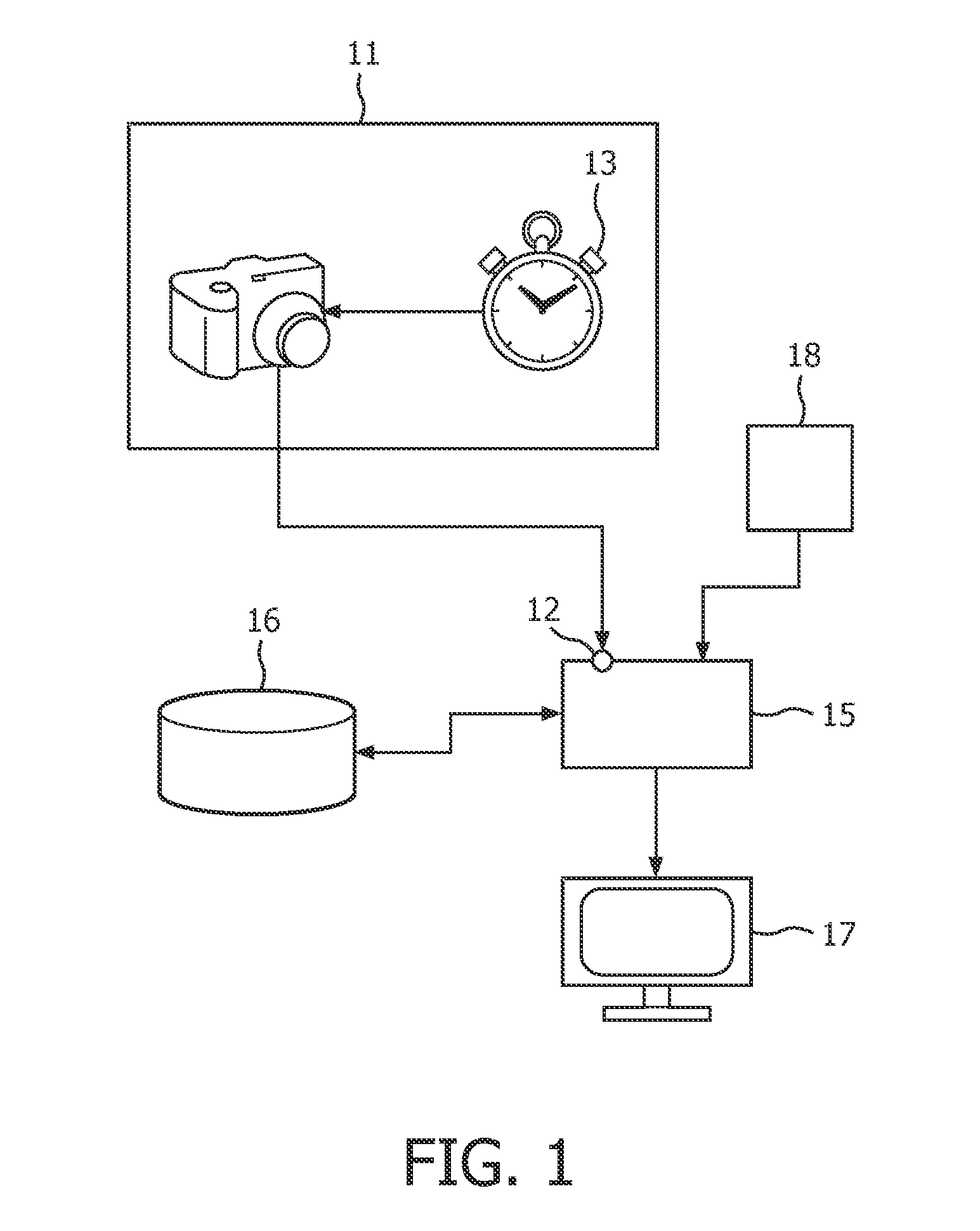
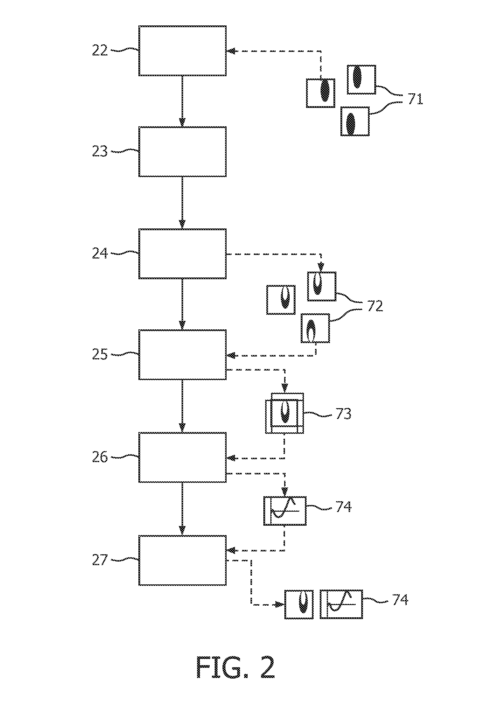
[0031]FIG. 1 schematically shows a system according to the invention. The system comprises a processor unit 15 with an input 12 for obtaining CT images of a lung. The CT images are obtained by a CT scanner 11, which may be part of or coupled to the system. A time stamp is added to the images obtained by the CT scanner 11. During the CT scan, patient respiratory traces are acquired with a marker block placed on, e.g., the upper abdomen. The projection images are retrospectively sorted into, e.g., ten respiratory phase-based bins of 3D CT image data (i.e., from 0% to 90% phase at 10% intervals). The time stamps are added by, e.g., an internal clock 13 of the CT scanner 11. The processing unit 15 may store the obtained images on a storage means 16, e.g. a hard disk. The images may be processed immediately upon receipt, or may be retrieved from the storage means 16 at a later point of time for being processed. The processing results in the generation of diagrams showing time courses of ...


PUM


Abstract

A system for displaying lung ventilation information, the system comprising an input (12) and a processing unit (15). The input being provided for receiving multiple CT images (71) of a lung, each CT image (71) corresponding to one phase of at least two different phases in a respiratory cycle. The processing unit (15) being configured to compare CT images (71) corresponding to different phases in the respiratory cycle for determining a deformation vector field for each phase, to generate for each phase a ventilation image (72) based on the corresponding deformation vector field, to spatially align the ventilation images (72), and to generate for at least one common position (62) in each one of the aligned ventilation images (72), a function (81) of a time course of a ventilation value for said common position (62), each ventilation value in the function (81) being based on the deformation vector fields corresponding to the aligned ventilation images (73).

Description

FIELD OF THE INVENTION[0001]This invention relates to a system for displaying lung ventilation information, the system comprising an input for receiving multiple CT images of a lung, each CT image corresponding to one phase of at least two different phases in a respiratory cycle, and a processing unit configured to:[0002]compare CT images corresponding to consecutive phases for determining a deformation vector field for each phase,[0003]generate, for each phase, a ventilation image based on the corresponding deformation vector field, and[0004]spatially align the ventilation images,[0005]and further comprising a display for displaying lung ventilation information.[0006]This invention further relates to a method of displaying lung ventilation information and to a computer program product.BACKGROUND OF THE INVENTION[0007]Japanese patent application JP 2005-028121 describes a system for measuring local lung ventilation. Said system uses a 3D CT scan of the lungs at the moments of inhala...

Claims


Application Information

Patent Timeline
Patent Type & Authority Patents(United States)
IPC IPC(8): G06K9/00
CPCA61B5/08A61B6/5235A61B6/541G06T2207/10081G06T2207/30061G06T7/33
Inventor KABUS, SVENLORENZ, CRISTIANSCHADEWALDT, NICOLEOPFER, ROLANDCARLSEN, INGWER CURTRENISCH, STEFFENSABCZYNSKI, JOERGBARSCHDORF, HANSVON BERG, JENSBLAFFERT, THOMASKLINDER, TOBIAS
Owner KONINKLIJKE PHILIPS ELECTRONICS NV
Why Eureka
Try Eureka