
Oil deterioration sensor

a technology of oil deterioration and detection apparatus, which is applied in the direction of resistance/reactance/impedence, instruments, material analysis, etc., can solve the problems of preventing accurate measurement of oil electrostatic capacitance, oil deterioration, and increase in total acid value, so as to achieve easy generation and easy processing

Inactive Publication Date: 2006-10-31
NGK SPARK PLUG CO LTD
View PDF28 Cites 23 Cited by
  • Summary
  • Abstract
  • Description
  • Claims
  • Application Information

AI Technical Summary

Benefits of technology

[0008]In the above-described configuration, there is provided an output compensation mechanism for compensating for a level change of the detection signal stemming from the temperature characteristic and / or time-course deterioration of the detection signal output circuit. Accordingly, even when the temperature of the measurement circuit system including the detection signal output circuit varies because of deposition in the vicinity of an object (an engine in the case of an automobile or the like) to be lubricated by oil, the deterioration detection on the basis of the electrostatic capacitance of the oil to be measured can always be performed accurately. Further, even when the characteristics of the measurement circuit system including the detection signal output circuit deteriorate with time because of exposure to high temperature, the detection of oil deterioration can be performed accurately by use of the above-described output compensation mechanism.
[0026]Meanwhile, the voltage output control section may be configured by use of a CPU. This configuration has an advantage in that changes in specifications such as the waveform, frequency, and phase of the measurement signal can be easily coped through modification of a program or the like.

Problems solved by technology

However, a driver who drives an automobile under the pressure of necessity but has no interest in the automobile, or a driver who is not mechanically inclined, generally first becomes aware of contamination of oil when a conscientious gas station attendant checks the oil.
Unbelievably, some drivers change oil only at the time of automobile inspection.
One cause of oil deterioration is an increase in total acid value.
However, when the length of the cable is increased, the influence of parasitic capacitance of the cable itself increases, thereby preventing accurate measurement of electrostatic capacitance of oil.
Further, because of long-term exposure to such high temperature, the characteristics of the peripheral circuits deteriorate to some degree, whereby the level of the detection output changes to no small extent.
Both the temperature change and the long-term deterioration of the circuit characteristic lead to the problem that accurate measurement of electrostatic capacitance becomes impossible.

Method used


Image

  • Oil deterioration sensor
  • Oil deterioration sensor
  • Oil deterioration sensor

Examples


first embodiment

(First Embodiment)

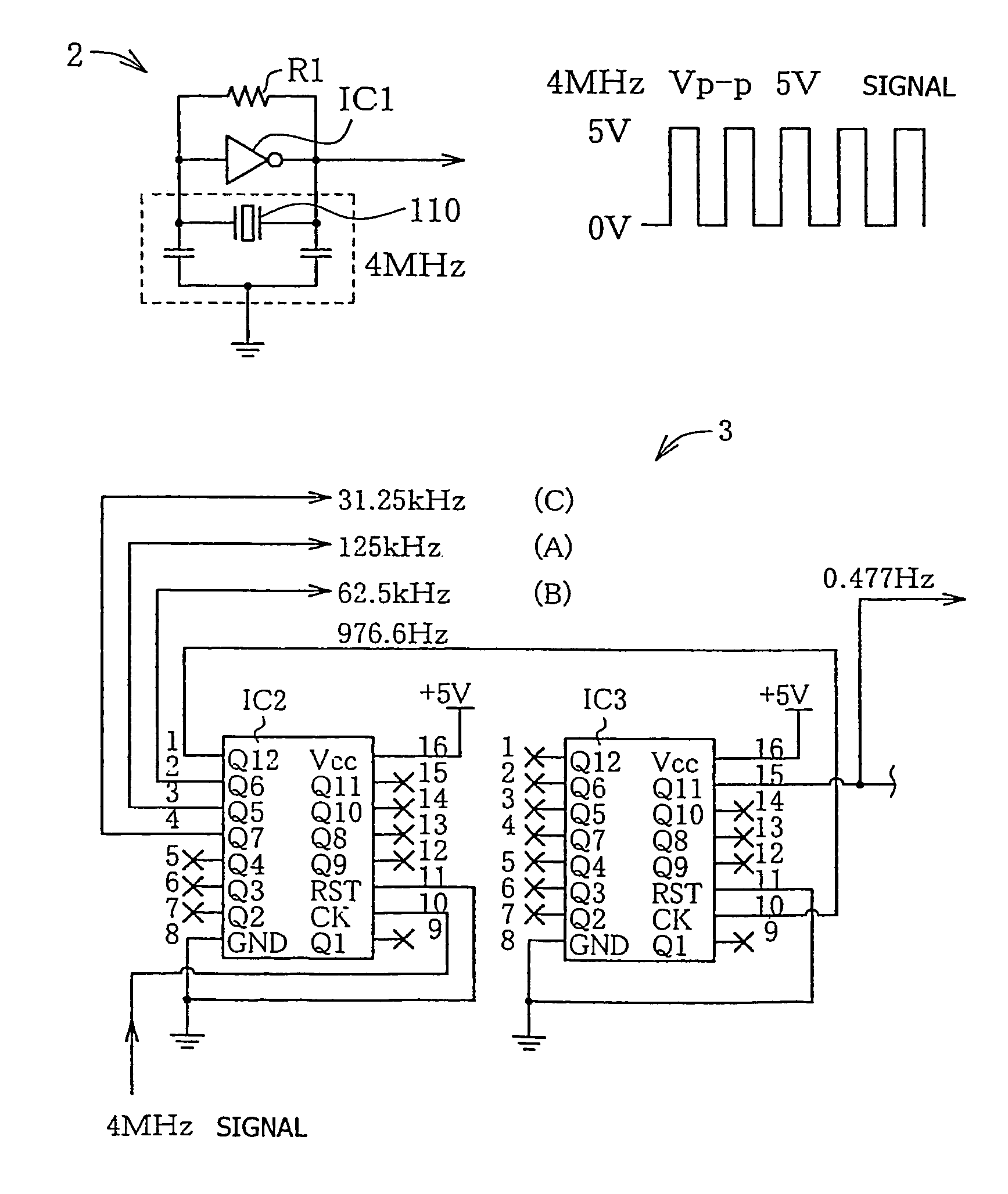
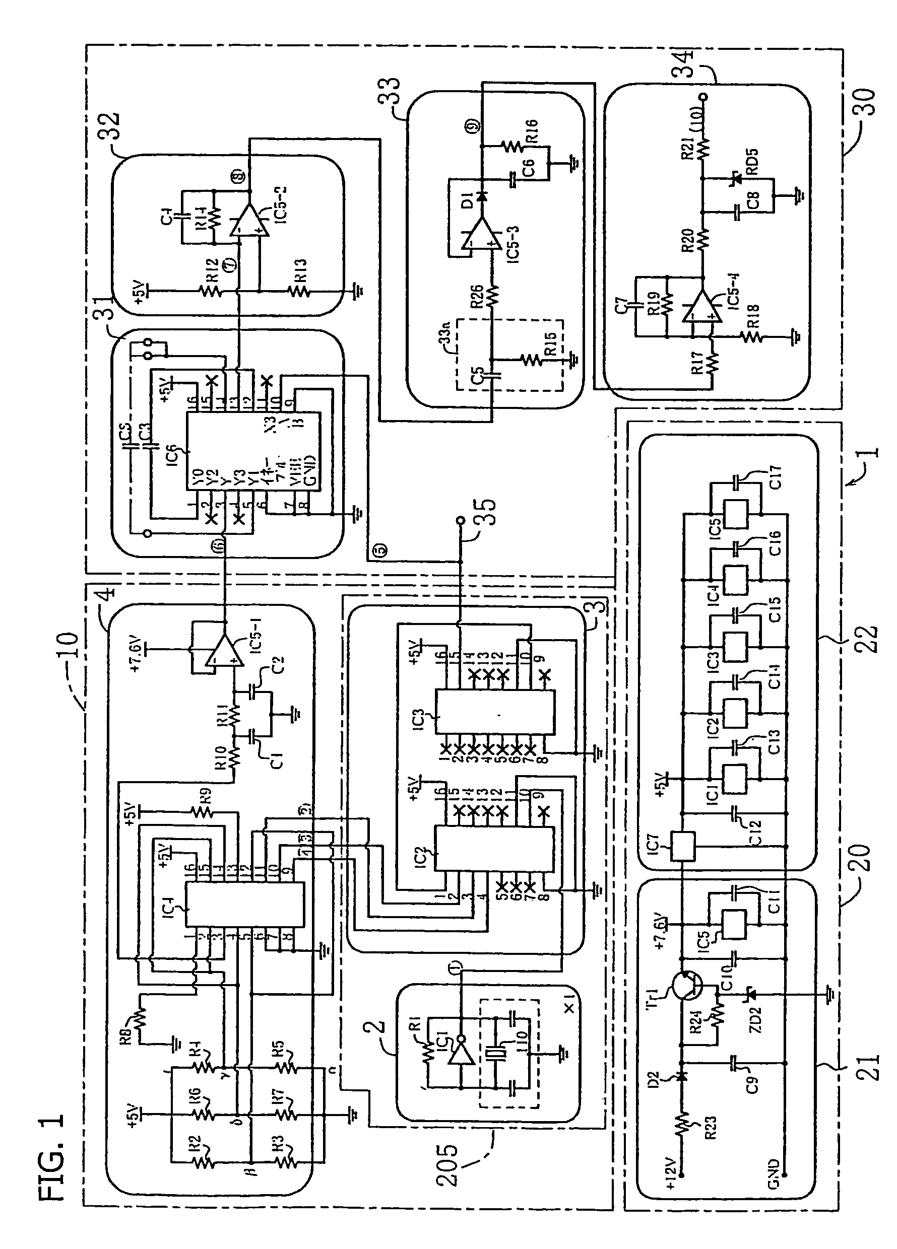
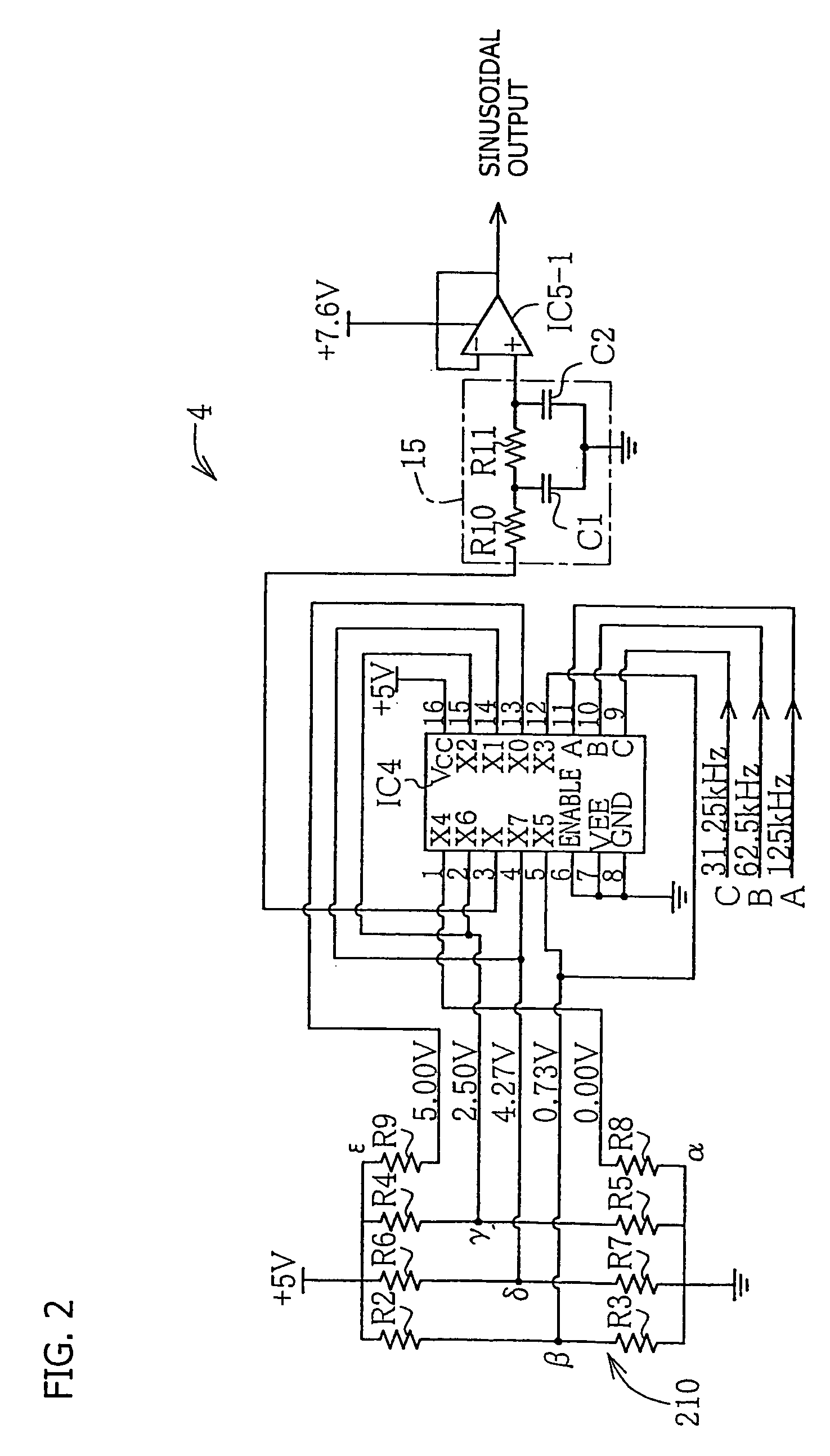
[0057]FIG. 1 is an overall circuit diagram showing one embodiment of an engine oil deterioration detection apparatus according to the present embodiment. The engine oil deterioration detection apparatus 1 mainly consists of three circuits; i.e., a measurement signal generation circuit 10, a detection signal output circuit 30, and a power supply circuit 20. As already described, the basic function of the engine oil deterioration detection apparatus 1 is to detect deterioration of engine oil on the basis of a change in electrostatic capacitance of a sensing capacitor CS shown in FIG. 14, which is formed by paired electrodes 51 and 52 and is dipped into the engine oil whose deterioration is to be detected. In the embodiment of FIG. 14A, the electrodes 51 and 52 of the sensing capacitor CS assume cylindrical shapes and are disposed coaxially. When the sensing capacitor is placed in oil, the oil enters the clearance between the electrodes 51 and 52, whereby a capacitor ...


PUM

PropertyMeasurementUnit
temperatureaaaaaaaaaa

Abstract

An engine oil deterioration detection apparatus includes a sensing capacitor CS formed of paired electrodes dipped into engine oil whose deterioration is to be detected, the engine oil deterioration detection apparatus detecting deterioration of the engine oil on the basis of a change in electrostatic capacitance of the sensing capacitor CS. A measurement signal generation circuit generates a measurement signal to be supplied to the sensing capacitor CS. A detection signal output circuit outputs a detection signal on the basis of a response wave signal produced from the sensing capacitor CS in response to supply of the measurement signal thereto, the detection signal reflecting the electrostatic capacitance of the sensing capacitor CS. A temperature compensation mechanism is provided to compensate for a level change of the detection signal stemming from a temperature characteristic and / or a time-course deterioration of the detection signal output circuit.

Description

TECHNICAL FIELD[0001]The present invention relates to an oil deterioration detection apparatus.BACKGROUND ART[0002]Maintenance work of exchanging lubrication oil of an engine of an automobile or the like at proper timing is very important for prolonging the service life of the engine. In general, an oil gauge, which is inserted into an oil pan, is removed periodically in order to visually check the degree of contamination of the oil, whereby the person making the check can grasp the degree of deterioration of the oil. However, a driver who drives an automobile under the pressure of necessity but has no interest in the automobile, or a driver who is not mechanically inclined, generally first becomes aware of contamination of oil when a conscientious gas station attendant checks the oil. Unbelievably, some drivers change oil only at the time of automobile inspection. Although many automobiles have an oil warning indicator on their dashboard panels, the indictor merely reports the resu...

Claims


Application Information

Patent Timeline
Patent Type & Authority Patents(United States)
IPC IPC(8): G01R27/26G01N27/22G01N33/28
CPCG01N33/2888G01N27/228
Inventor HAYASHI, SHINICHISASAKI, HISASHI
Owner NGK SPARK PLUG CO LTD
Learn More