Electrical device mounting structure on a motorcycle

a technology for mounting structures and electrical devices, which is applied in the direction of steering devices, cycle equipments, frictional rollers based transmission, etc., can solve the problems of deteriorating the operational feeling of the operator, the uncontrollable transmission of operational vibrations of the motorcycle engine to the electrical device, and the inability to control the operation of the motorcycle engine. to achieve the effect of improving the operational feeling of the operating elemen

Inactive Publication Date: 2014-08-12
HONDA MOTOR CO LTD
View PDF35 Cites 7 Cited by
  • Summary
  • Abstract
  • Description
  • Claims
  • Application Information

AI Technical Summary

Benefits of technology

[0006]The present invention has been derived with the above circumstance in view. An aspect of the present invention is to provide an electrical device mounting structure on a motorcycle of simple structure which absorbs vibrations transmitted from a vehicle body to an electrical device and improves the operational feeling of an operating element to the motorcycle operator.
[0010]Further, according to the present invention, the resilient support member secured to the vehicle body or the member connected to the vehicle body can isolate a plurality of different kinds of vibrations by adjusting the thickness and shape of the resilient support member, as well as the position where the resilient support member is secured to the vehicle body or the member connected to the vehicle body. That is, the present invention provides a benefit wherein it is easy to design and manufacture resilient support members capable of isolating vibrations for various kinds of electrical devices.
[0011]Furthermore, according to the present invention, use of the resilient support member reduces the number of required resilient members, which simplifies the overall structure and reduces the overall cost of the motorcycle.
[0013]Accordingly, it is possible to provide a sufficient distance from the first portion, i.e., a fixed point to the electrical device, such that the resonance point of the resilient support member is set to a relatively low level. As a result, vibrations are effectively isolated from the electrical device when the motorcycle body is vibrating at a relatively low frequency.
[0015]Accordingly, it is possible to provide a short distance from the first portion, i.e., a fixed point to the electrical device, such that the resonance point of the resilient support member is set to a relatively high level. As a result, vibrations are effectively isolated from the electrical device when the motorcycle body is vibrating at a relatively high frequency. Also, because of the short distance from the fixed point to the electrical device, the operator of the motorcycle is able to acquire a satisfactory feeling of rigidity, i.e., a better operating feeling when the operator operates a switch operating element of a control switch unit.

Problems solved by technology

In the structure disclosed by JP '173, vibrations of the vehicle body due to the motorcycle traveling on a road and operational vibrations of a motorcycle engine are undesirably transmitted to the electrical device.
In the structure disclosed by JP '762, vibrations transmitted from the vehicle body to the electrical device are absorbed by the resilient member, but when an operator operates a switch operating element mounted on the electrical device, such as a button, a knob, a dial, or the like, a large part of the operator's operating force is also absorbed by the resilient member, wherein a weakened feeling of rigidity results, which deteriorates the operational feeling to the operator.

Method used


Image

  • Electrical device mounting structure on a motorcycle
  • Electrical device mounting structure on a motorcycle
  • Electrical device mounting structure on a motorcycle

Examples


first embodiment

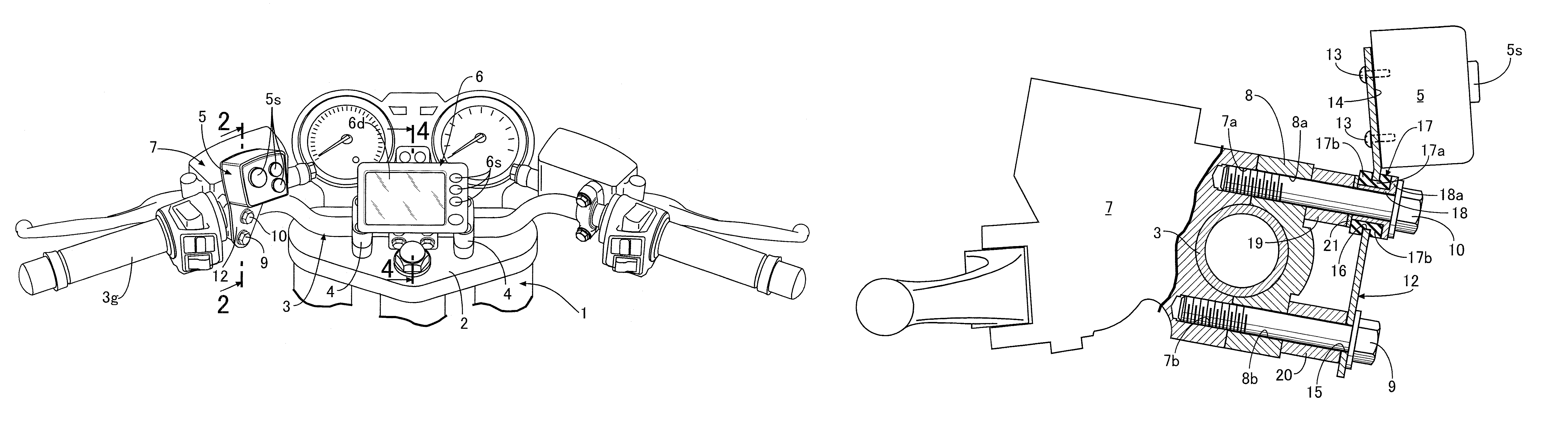
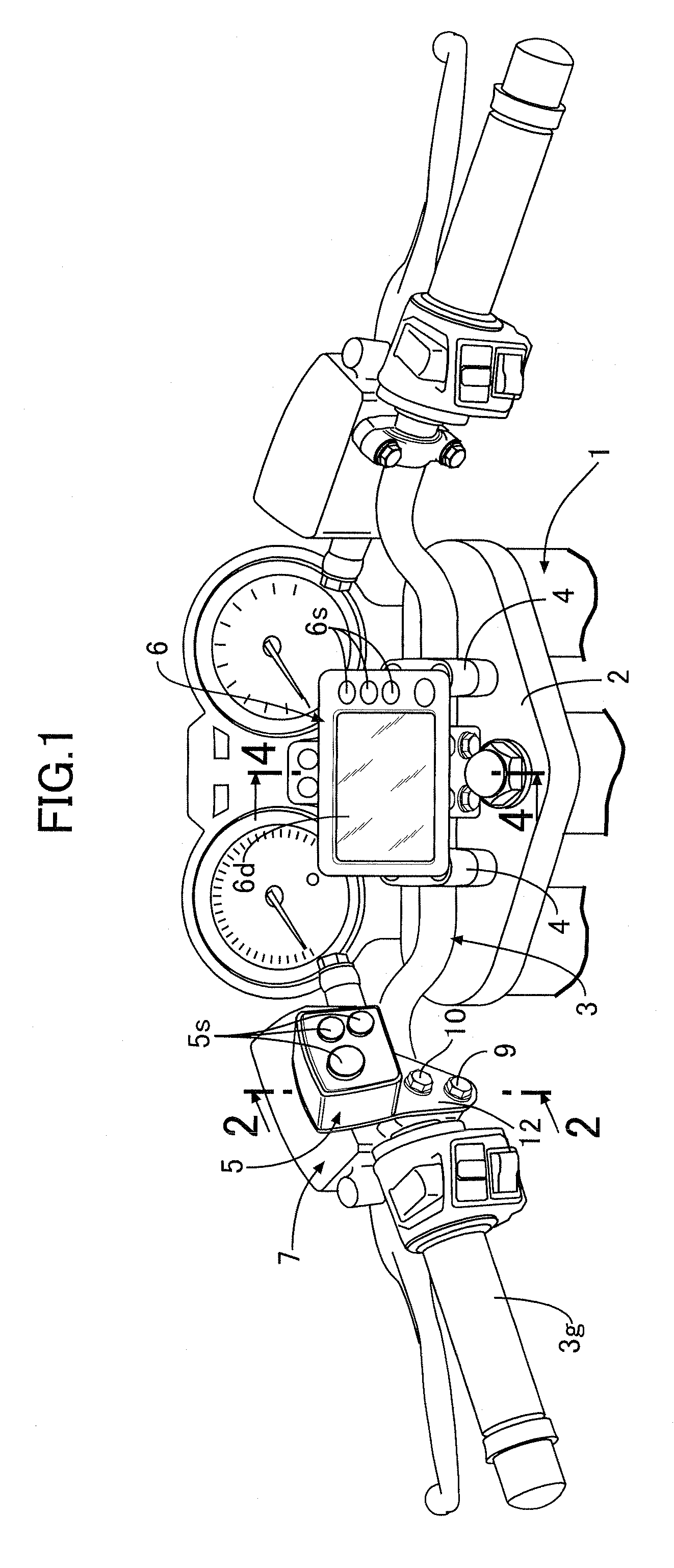
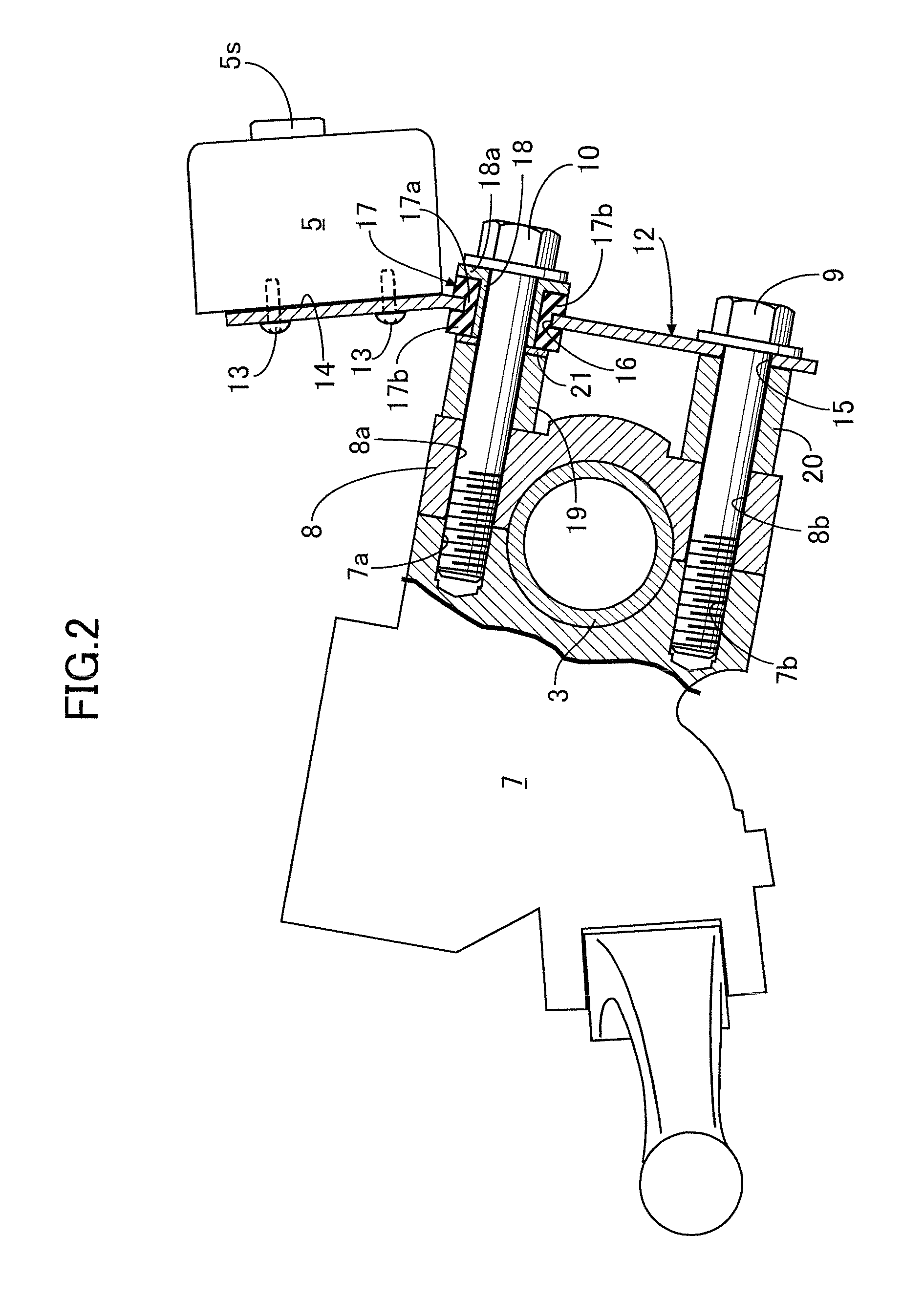
[0029]First, the mounting structure of the control switch unit 5 will be described with reference to FIGS. 2 and 3. A clutch master cylinder 7 and a holder 8 are secured to the handlebar 3 and fastened to each other by a pair of upper and lower bolts 10 and 9, wherein the handlebar 3 is sandwiched therebetween.

[0030]A resilient support plate 12 for supporting the control switch unit 5 is made of, for example, spring steel to obtain a resiliency so the support plate 12 can be flexed in response to the vibration of the handlebar 3. The resilient support plate 12 has an electric device mounting portion 14 at an upper end for securing thereto the control switch unit 5 using a plurality of screws 13. Also, the resilient support plate 12 is configured to have a shape wherein a width thereof decreases in a direction taken from the electric device mounting portion 14 toward a lower end. A single first mounting bore 15 is provided in the lower end of the resilient support plate 12. Also, a ...

second embodiment

[0042]A structure for mounting the navigation unit 6, according to the present invention, will be described below with reference to FIGS. 4 and 5. Left and right sets of front and rear holders 107, 8; 107, 8 are disposed at the central portion of the handlebar 3, causing each set to clamp the handlebar 3 from the front and rear. The holders 107, 8; 107, 8 are secured to the handlebar 3 by lower and upper sets of left and right bolts 9, 10; 9, 10. The resilient support plate 12′ supporting the navigation unit 6 is mounted to the handlebar 3 by the holders 107, 8; 107, 8 and the bolts 9, 10; 9, 10.

[0043]The resilient support plate 12′ has the same structure as that of the first embodiment except that the thickness of the resilient support plate 12′ is larger than that of the resilient support plate 12 of the first embodiment in order to support the navigation unit 6, which is heavier than the control switch unit 5 described above with respect to the first embodiment. In this embodimen...

third embodiment

[0046]the present invention shown in FIGS. 6 and 7 will be described below.

[0047]In the third embodiment, in order to facilitate operation of the switch operating elements 5 using a finger of the operator's hand while gripping the grip 3g, the control switch unit 5 is mounted as close as possible to the grip 3g by a resilient support plate 12″. The support plate 12″ is resiliently supported by a mirror-mounting boss 35 formed on a clutch master cylinder 7 and a stay 34a of a rearview mirror 34 threadedly secured to the mirror-mounting boss 35. More specifically, the resilient support plate 12″ includes a vertical portion 36 having a first mounting bore 15 defined in a lower end; a horizontal portion 37 having a second mounting bore 16 defined in a front end and which is bent forward from an upper end of the vertical portion 36 along a thickness direction of the resilient support plate 12″; and a electric device mounting portion 14 extending from the upper end of the vertical portion...


PUM


Abstract

An electrical device mounting structure on a motorcycle which includes a resilient support member having a spring-flexural resilience and supporting an electrical device unit. The resilient support member has a first portion secured to a vehicle body or a member connected to the vehicle body. The resilient support member also has a second portion provided separate from the first portion and closer to the electrical device. The second portion is supported on the vehicle body or the member connected to the vehicle body via an elastic member having an attenuating property.

Description

BACKGROUND OF THE INVENTION[0001]1. Field of the Invention[0002]The present invention relates to an improvement of an electrical device mounting structure on a motorcycle, wherein an electrical device is mounted on the vehicle body or a member connected to the vehicle body via a support member.[0003]2. Description of the Related Art[0004]Japanese Utility Model No. 2549173 (JP '173) discloses a structure in which a support member for supporting an electrical device is secured to the vehicle body or a member connected to the vehicle body. In the structure disclosed by JP '173, vibrations of the vehicle body due to the motorcycle traveling on a road and operational vibrations of a motorcycle engine are undesirably transmitted to the electrical device.[0005]Also, Japanese Patent Application Laid-open No. 2004-237762 (JP '762) discloses a structure in which an entire support member for supporting an electrical device is mounted to the vehicle body or a member connected to the vehicle bod...

Claims


Application Information

Patent Timeline
Patent Type & Authority Patents(United States)
IPC IPC(8): B62J11/00B62J99/00B62K11/14B62K23/02
CPCB62K23/02B62J11/00B62K11/14Y10S224/929
Inventor HOSHI, TOMOHIRO
Owner HONDA MOTOR CO LTD
Why Eureka
Try Eureka