Hybrid transmission

a hybrid transmission and transmission shaft technology, applied in the direction of electric propulsion mounting, transportation and packaging, gearing, etc., can solve the problems of hybrid transmission performance degradation, speed control instability, and the like, and achieve the effects of enhancing fuel efficiency, reducing costs, and generating electricity

Active Publication Date: 2014-08-12
HYUNDAI MOTOR CO LTD
View PDF4 Cites 4 Cited by
  • Summary
  • Abstract
  • Description
  • Claims
  • Application Information

AI Technical Summary

Benefits of technology

[0012]Various aspects of the present application are directed to provide a hybrid transmission having a single motor without a torque converter to reduce costs. The motor can be utilized to provide a smooth start of a vehicle and also to generate electricity. Slips caused by the torque converter and a friction clutch can be eliminated. The regenerative braking can be performed to enhance the fuel efficiency of the vehicle. A torque assistant during acceleration can be performed by the motor to enhance the drivability of the vehicle. A power input path from the engine and a power input path from the motor can be set differently from each other to utilize the optimal efficiency operating point of the motor without being limited to a certain number of revolutions per minute of the engine, leading to maximization of the fuel efficiency.

Problems solved by technology

However, hybrid transmissions having such a structure experience some problems.
Also, when a charged amount of the battery is insufficient or a capacity of the motor is small, namely when low-speed hill climbing using the engine torque is required continuously, performance of the hybrid transmissions can be degraded.
Performance degradation includes an impact due to a slip of the clutch, instability of speed control, or a thermal deterioration of the clutch.
In addition, since an input shaft for the engine power and an input shaft for the motor power are identical, utilization of an optimal efficiency operating point of the motor, in which the motor has a number of revolutions per minute higher than those of the engine, can be restricted and thus enhancement of the fuel efficiency cannot be sufficiently realized.

Method used


Image

  • Hybrid transmission
  • Hybrid transmission
  • Hybrid transmission

Examples


Embodiment Construction

[0049]Reference will now be made in detail to various embodiments of the present invention(s), examples of which are illustrated in the accompanying drawings and described below. While the invention(s) will be described in conjunction with exemplary embodiments, it will be understood that present description is not intended to limit the invention(s) to those exemplary embodiments. On the contrary, the invention(s) is / are intended to cover not only the exemplary embodiments, but also various alternatives, modifications, equivalents and other embodiments, which may be included within the spirit and scope of the invention as defined by the appended claims.

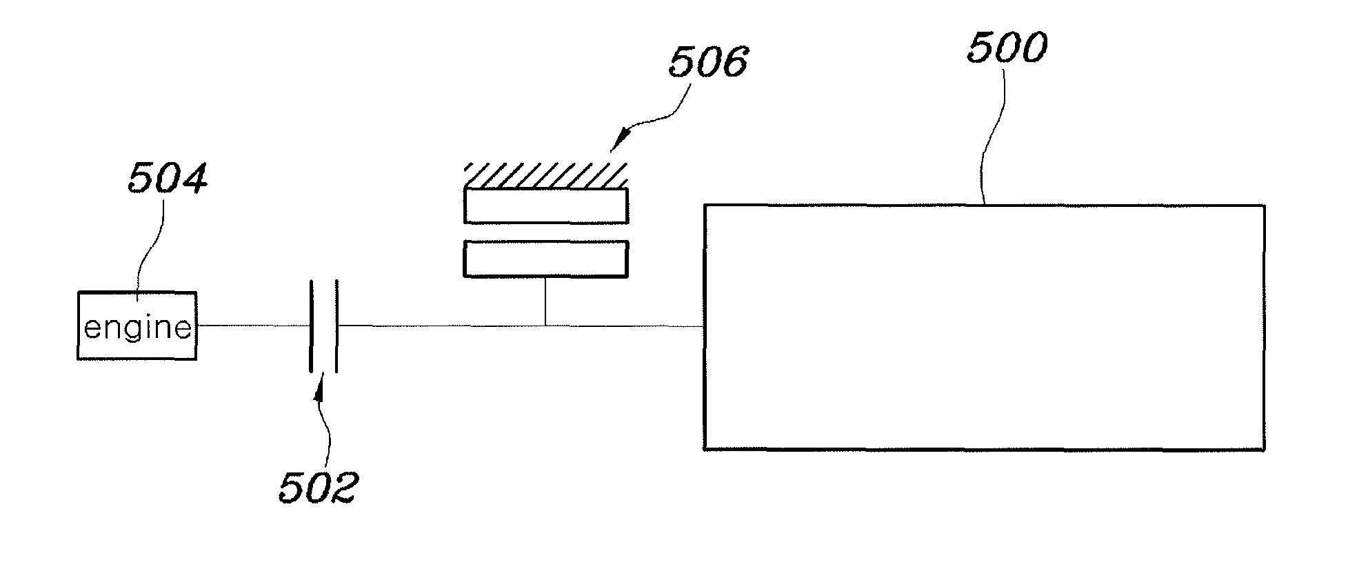
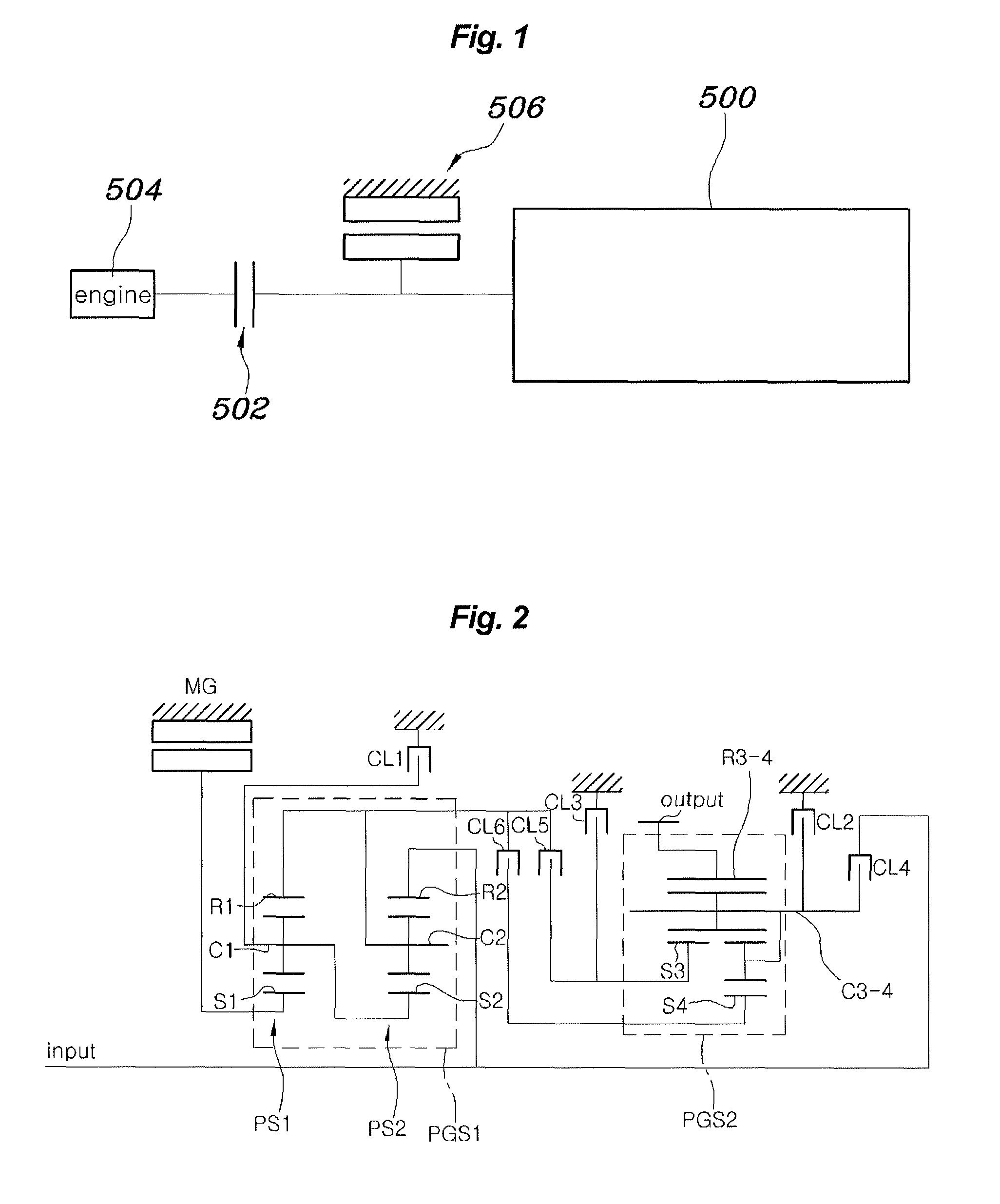
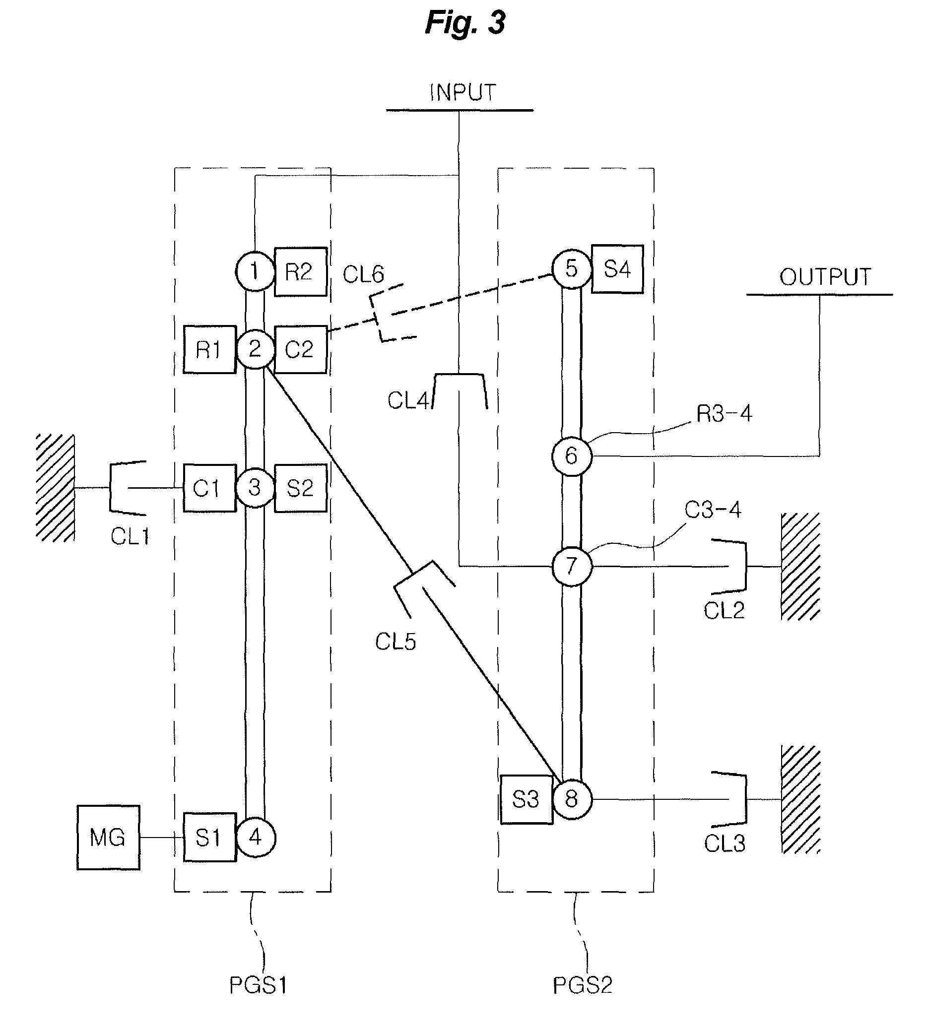
[0050]Referring to FIGS. 2 to 13, various embodiments of a hybrid transmission of the present application have a common configuration. This common configuration includes a first planetary gear set PGS1 and a second planetary gear set PGS2. The first planetary gear set PGS1 is constituted of a complex planetary gear train connected to ...


PUM


Abstract

A hybrid transmission includes a first planetary gear set and a second planetary gear set. The first planetary gear set is constituted of a complex planetary gear train connected to an input element, a motor / generator, and a first clutch, and has four or more rotation elements. The first rotation element of the first planetary gear set is selectively connected to the input element and the first clutch is installed to selectively stop rotation of a third rotation element of the first planetary gear set. The fourth rotation element of the first planetary set is selectively connected to the motor / generator. The second planetary gear set is connected to an output element, and has four or more rotation elements.

Description

CROSS-REFERENCE TO RELATED APPLICATIONS[0001]The present application claims priority of Korean Patent Application Number 10-2011-0131882 filed on Dec. 9, 2011, the entire contents of which application is incorporated herein for all purposes by this reference.BACKGROUND OF INVENTION[0002]1. Field of Invention[0003]The present invention relates, in general, to a hybrid transmission, and more particularly, to a structure of a transmission adapted to transfer power from each of an engine and a motor to driving wheels.[0004]2. Description of Related Art[0005]In general, hybrid vehicles are vehicles using two or more energy sources and are mostly used in a combination of an existing engine using fossil fuels and at least one motor using electrical energy, although various other methods may be used depending on the combination of many energy sources.[0006]Depending on whether the engine and / or the motor is operated, the hybrid vehicles can realize an electric vehicle (EV) mode driven by on...

Claims


Application Information

Patent Timeline
Patent Type & Authority Patents(United States)
IPC IPC(8): F16H3/72
CPCF16H3/725B60K6/365B60K6/48B60K2006/4816F16H2200/0052F16H2200/006F16H2200/201F16H2200/2012F16H2200/2023F16H2200/2046F16H2200/2048Y02T10/6221Y02T10/6256Y02T10/62F16H3/44F16H3/72
Inventor PARK, JONG, SOOL
Owner HYUNDAI MOTOR CO LTD
Why Eureka
Try Eureka