Method for managing a data transmission from a sender device, corresponding computer-readable storage medium and sender device

a data transmission and sender device technology, applied in the direction of digital transmission, selective content distribution, electrical apparatus, etc., can solve the problems of affecting the effect of data transmission, affecting the speed of data transmission, and the unpredictable nature of effective switch-over, so as to maximize the use of allocated bandwidth, minimize the duration, and improve the effect of bandwidth consumption

Inactive Publication Date: 2014-08-12
CANON KK
View PDF5 Cites 0 Cited by
  • Summary
  • Abstract
  • Description
  • Claims
  • Application Information

AI Technical Summary

Benefits of technology

[0019]Another object of the present invention is to provide a technique for transmitting data between a sending device and a receiving device to maintain constant end-to-end latency in the context of a combined change in bandwidth and source encoding, whatever the rates of the applications clock and of the network clock.
[0043]Thus, the fact of having a data block period (for example a macro-block) adapted to the precision of the clock which defines the clock rate of the transport of the encoded data and serves as a common reference for each device of the system, prevents any deterioration of the overall precision of the system.

Problems solved by technology

A divergence of this kind may lead to a modification of the end-to-end latency of the system.
However, the random nature of the transmission channel may cause the network layer to modify the bandwidth allocated to an application in order to adapt its retransmission scheme or error-correction scheme to the new conditions of transmission.
One of the main problems related to the modification of the source encoding (i.e. the encoding parameters used by the encoder to encode the applications data blocks) following a reallocation of the bandwidth is to maintain a constant quality of service, i.e. to prevent any interruption of the application for the user.
Furthermore, in a system with low transmission latency, i.e. a system where the memory resources are small, there is little room for maneuver to compensate for modifications in end-to-end latency, even transient modifications, which lead to overflows of buffer memory of the sending device and / or the receiving device.
One drawback of this prior art approach lies in the unpredictable nature of the effective switch-over at the level of transport between applications data that have undergone a first source encoding and applications data that have undergone a second source encoding.
Thus, in the above mentioned context of a combined change of bandwidth and source encoding, using the above-mentioned known approach, it can happen that the source encoding is not consistent with the bandwidth allocated during several transport periods, thus leading to a modification of the end-to-end latency or a poor use of the bandwidth allocated to the application.

Method used


Image

  • Method for managing a data transmission from a sender device, corresponding computer-readable storage medium and sender device
  • Method for managing a data transmission from a sender device, corresponding computer-readable storage medium and sender device
  • Method for managing a data transmission from a sender device, corresponding computer-readable storage medium and sender device

Examples


Embodiment Construction

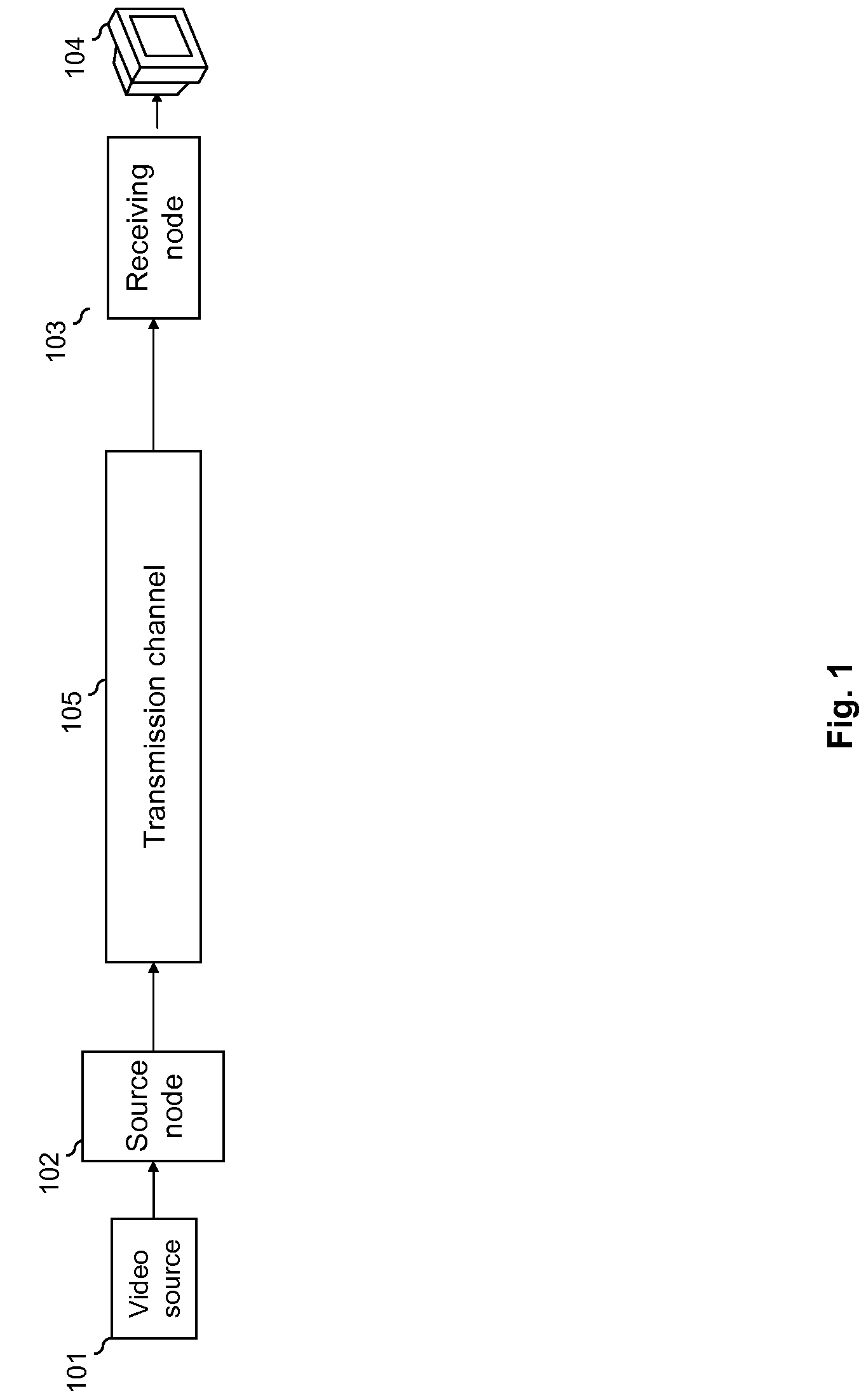
[0065]FIG. 1 describes the architecture of a real-time video distribution system according to one particular embodiment of the invention. This distribution system is used to display the content of a video source on a screen.

[0066]An architecture of this kind is given purely by way of an illustration and the present invention can be implemented in other data transmission systems, whatever the type of data transported, since the invention is not limited to the real-time distribution of video data.

[0067]More particularly, the real-time video distribution system comprises:[0068]a TDM (Time Division Multiplexing) type synchronous transmission channel 105;[0069]a sending node 102, here below also called a sending device, comprising a first end connected to the channel 105 and a second end connected to a video source 101 (for example a DVD player) generating raw audiovisual applications data;[0070]a receiving node 103, here below also called a receiving device, comprising a first end conne...


PUM


Abstract

A sending device receives applications data blocks to be transmitted to a receiving device according to a clock rate defined by transport periods, the applications data blocks being encoded before transmission by application of a first source encoding up to the processing of a change request. The sending device determines a drift between a number of applications data blocks received by the sending device and a number of applications data blocks transmitted after encoding by the sending device. The sending device determines, taking account of the determined drift, a transition applications data block from which a second source encoding is applied in response to the change request. The transmission of the stream is then adapted in such a way that the transmission of the encoded transition data block is aligned with a start of a transport period.

Description

CROSS-REFERENCE TO RELATED APPLICATIONS[0001]This application claims the benefit under 35 U.S.C. §119(a)-(d) of French Patent Application No. 1053947, filed on May 21, 2010 and entitled “Method for managing a data transmission from a sender device, corresponding computer program product, storage means and sender device”.[0002]The above cited patent application is incorporated herein by reference in its entirety.BACKGROUND OF THE INVENTION[0003]1. Field of the Invention[0004]The present invention relates to data transmission between a sending device and a receiving device.[0005]The invention can be applied especially but not exclusively to data transmission in a system of video distribution between a source application (that generates for example a video content coming from a DVD player) placed upstream to the sending device and at least one receiving application (for example a television set) placed downstream to the receiving device.[0006]The present invention also relates to manag...

Claims


Application Information

Patent Timeline
Patent Type & Authority Patents(United States)
IPC IPC(8): H04J3/07
CPCH04N21/23406H04N21/44004
Inventor GUIGNARD, ROMAINCLOSSET, ARNAUD
Owner CANON KK
Why Eureka
Try Eureka