
Receiver receiving a signal including physical layer frames, and including a convolutional deinterleaver and a deinterleaver selector

a technology of physical layer frames and receivers, applied in the direction of code conversion, error correction/detection using convolutional codes, code conversion, etc., can solve the problems of increasing complexity and memory requirements at both transmitters and receivers, reducing the impact of latency, and reducing memory requirements. , the effect of constant latency

Active Publication Date: 2019-01-08
SATURN LICENSING LLC
View PDF13 Cites 3 Cited by
  • Summary
  • Abstract
  • Description
  • Claims
  • Application Information

AI Technical Summary

Benefits of technology

The patent introduces a method for incorporating discontinuities, such as interleaving frame transitions, into convolutional interleaving without transmitting dummy symbols to ensure that symbols from consecutive interleaving frames are not interleaved. It identifies symbols affected by discontinuity punctures and buffers or stores them to be read back into the delay portions of the deinterleaver to compensate for the discontinuity punctures. This arrangement reduces memory requirements compared to using a single dedicated buffer for all stored symbols and allows for reconfiguration and changing interleaving frame lengths while maintaining a constant latency through the deinterleaver. Overall, the patent provides a more efficient and flexible way to handle data transmission.

Problems solved by technology

However, in the event of burst errors this threshold can be exceeded and the error correction code may fail to reliably correct the errors in the data.
However, although interleaving is an important tool in modern communication systems, the benefits of interleaving often come at the cost of increased complexity and memory requirements at both a transmitter and a receiver.

Method used


Image

  • Receiver receiving a signal including physical layer frames, and including a convolutional deinterleaver and a deinterleaver selector
  • Receiver receiving a signal including physical layer frames, and including a convolutional deinterleaver and a deinterleaver selector
  • Receiver receiving a signal including physical layer frames, and including a convolutional deinterleaver and a deinterleaver selector

Examples


Embodiment Construction

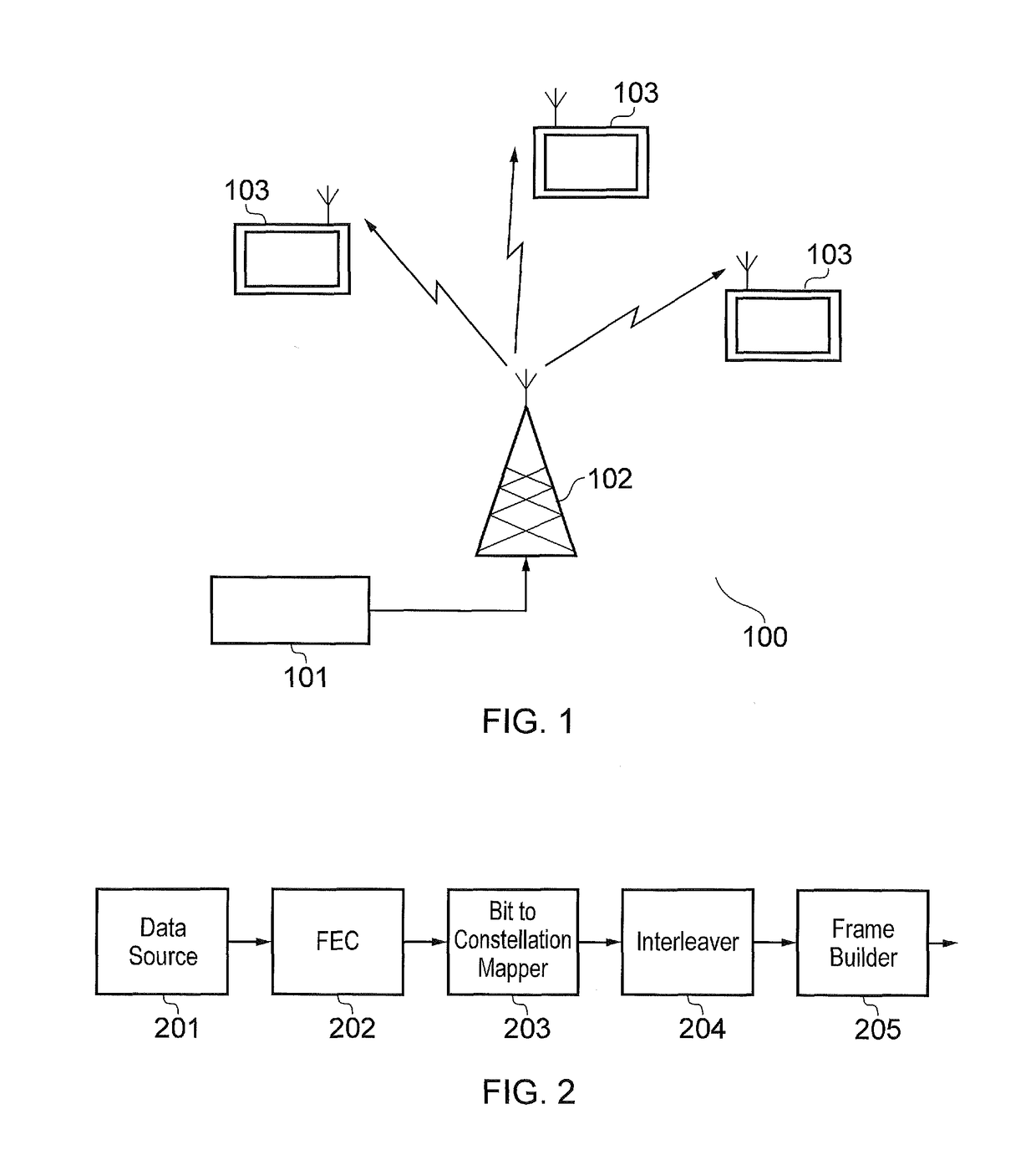
[0023]FIG. 1 provides a block diagram of a simplified digital communication network 100. A network as illustrated by FIG. 1 may operate in accordance with any known communication standard such as the proposed Advanced Televisions Systems Committee 3 (ATSC3.0) standard or DVB-T standard for example. A core network 101 transmits a signal, such as a digital audio-visual signal representing television content, to a transmitter 102 that transmits the signal. The transmitted signal is received by the receivers 103, which in the case of a digital audio-visual signal may be a television set with a display, a receiver within a television set, a television receiver device or any other compatible device such as for example a mobile terminal (such as a cellular telephone) including or connectable to a television receiver device. The receiver is operable to receive the transmitted signal and provide the content represented by the signal to a display. Although FIG. 1 shows the wireless transmissi...


PUM


Abstract

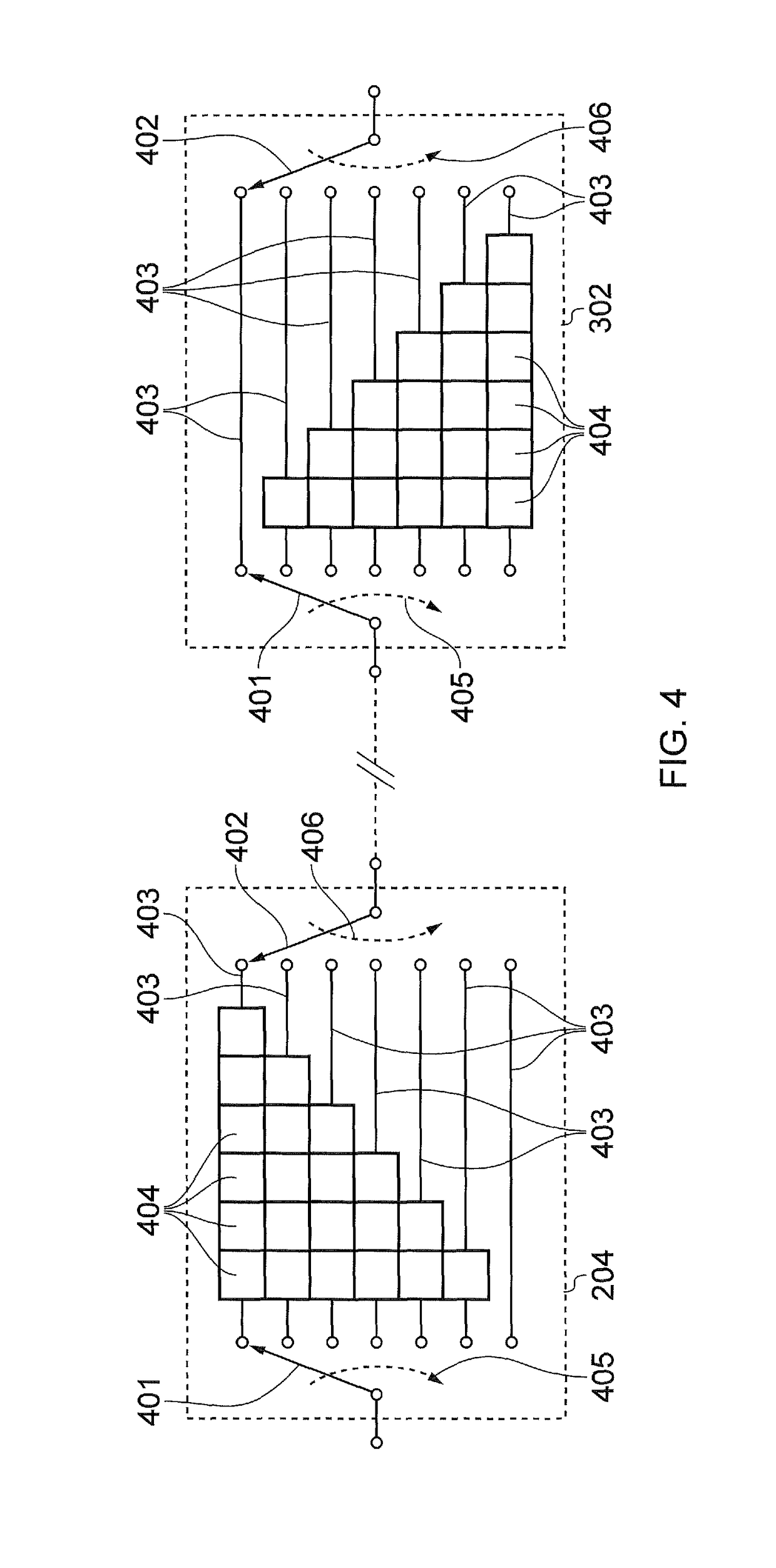
A receiver receives a signal including an interleaved symbol stream. The receiver includes a convolutional deinterleaver including a plurality of delay portions each of which is arranged to delay symbols from the symbol stream from an input to an output by a different amount, the delay portions being arranged in a sequence. An input selector inputs the symbols from the symbol stream to the delay portions so that successive symbols are input in accordance with the sequence of the delay portions. An output selector configured to read the symbols from the delay portions by successively selecting the symbols from the outputs of the delay portions in accordance with the sequence of the delay portions to form a deinterleaved symbol stream.

Description

FIELD OF THE DISCLOSURE[0001]The present disclosure relates to receivers and methods for receiving signals that comprise an interleaved symbol stream.BACKGROUND OF THE DISCLOSURE[0002]In digital communication systems reliable communication of data is important and a number of methods exist to improve the reliability, for example, error correction coding and data interleaving. Error correction coding allows errors in received data to be reliably corrected dependent on a number of errors in a code word being below a certain threshold. However, in the event of burst errors this threshold can be exceeded and the error correction code may fail to reliably correct the errors in the data. Interleaving of symbols and frames in a communication system assists in distributing burst errors between code words, therefore reducing the possibility that the error threshold of the error correction code will be exceeded. However, although interleaving is an important tool in modern communication syste...

Claims


Application Information

Patent Timeline
Patent Type & Authority Patents(United States)
IPC IPC(8): H03M13/27H04L1/00H03M13/23H03M13/00
CPCH03M13/2732H03M13/23H03M13/2792H04L1/0045H03M13/6508H03M13/2782H03M13/2789H03M13/2785
Inventor TAYLOR, MATTHEW PAUL ATHOL
Owner SATURN LICENSING LLC
Learn More