Interchangeable lens, camera body, and camera system

a technology of interchangeable lenses and camera bodies, applied in the direction of printers, instruments, camera focusing arrangements, etc., can solve the problems of becoming impossible to perform satisfactory communication, unsatisfactory communication, and much unnecessary communication undesirably performed

Inactive Publication Date: 2014-08-12
NIKON CORP
View PDF18 Cites 0 Cited by
  • Summary
  • Abstract
  • Description
  • Claims
  • Application Information

AI Technical Summary

Benefits of technology

[0023]According to the present invention, it is possible to perform satisfactory communication.

Problems solved by technology

Accordingly unnecessary communication is undesirably performed even when the camera body does not require this information related to the driven positions, and there has been the problem that it may become impossible to perform satisfactory communication.
Moreover, if transmission and reception of the information related to the various driven positions is performed by using the contact points for general purpose communication described above, it becomes necessary to transmit and receive much superfluous data, such as for example data that specifies that the driven position information is being requested and so on, in other words much unnecessary communication is undesirably performed, so that the problem arises that it may become impossible to perform satisfactory communication.

Method used


Image

  • Interchangeable lens, camera body, and camera system
  • Interchangeable lens, camera body, and camera system
  • Interchangeable lens, camera body, and camera system

Examples


embodiment 1

[0030

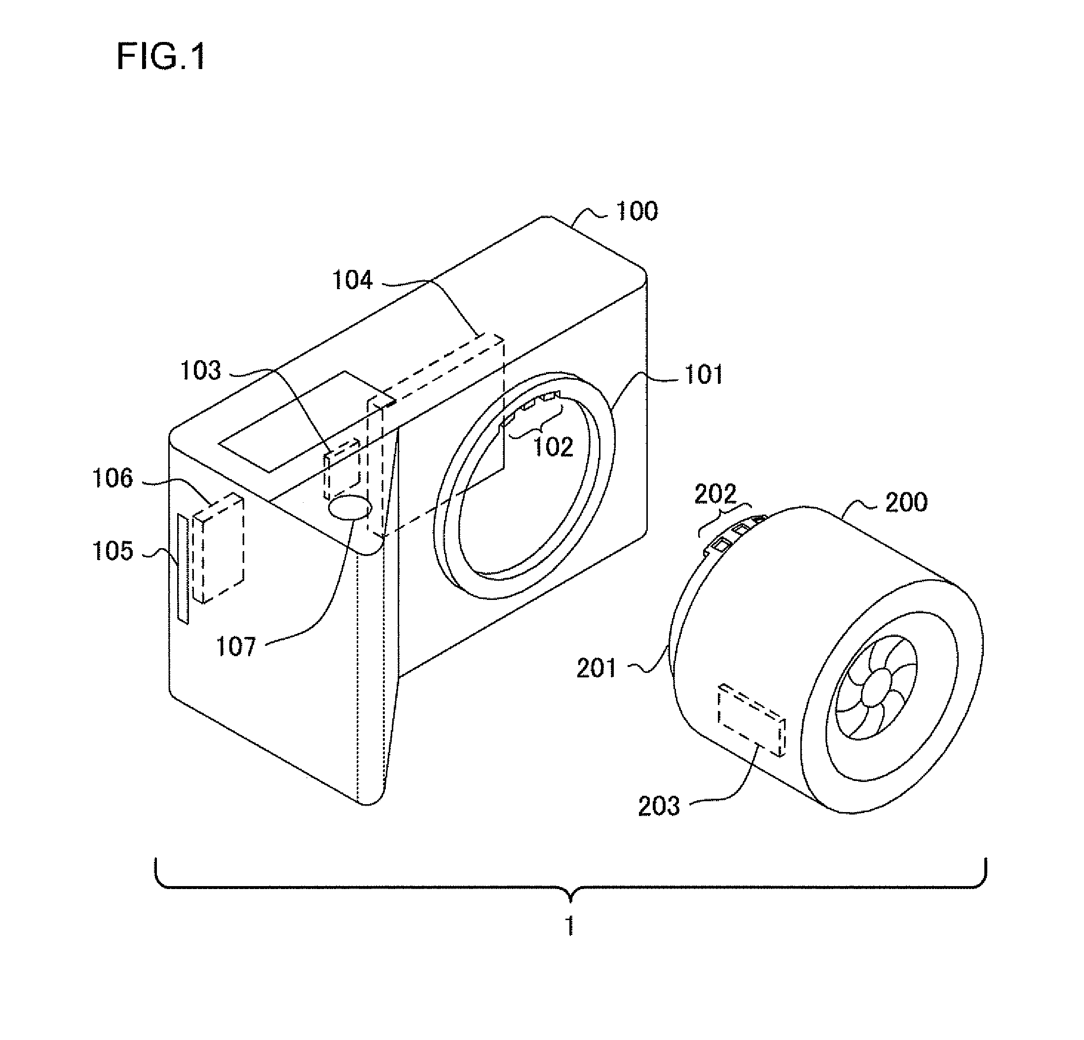
[0031]FIG. 1 is a perspective view showing the external appearance of a camera system according to a first embodiment of the present invention. This camera system 1 includes a camera body 100 and an interchangeable lens 200. The interchangeable lens 200 is fitted to the camera body 100 so as to be detachable. The fitting of the interchangeable lens 200 to the camera body 100 is performed by setting a lens side lens mount 201 of the interchangeable lens 200 into a body side lens mount 101 of the camera body 100.

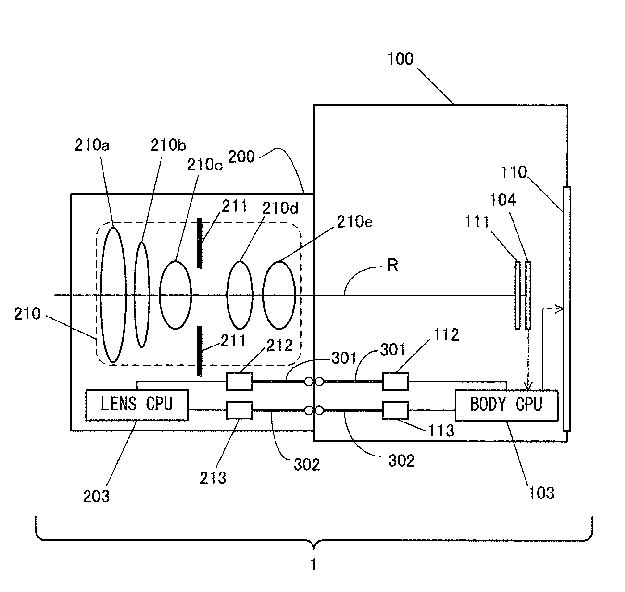
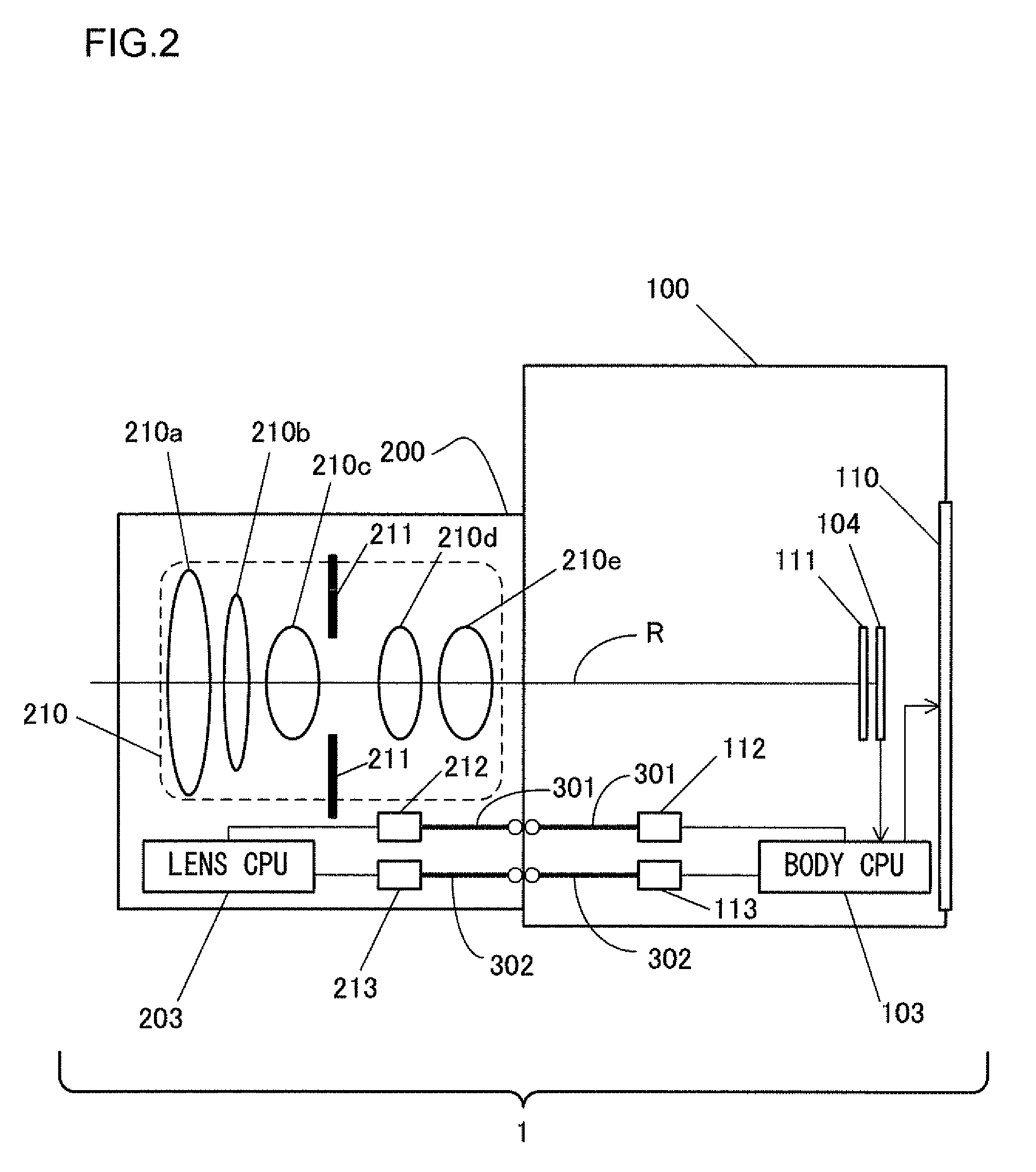
[0032]A contact point group 102 that includes a plurality of contact points for data communication and power supply is provided in the neighborhood of the body side lens mount 101. A contact point group 202 that includes a plurality of contact points, each corresponding to one of the contact points in the camera body side contact points group 102, is provided in the neighborhood of the lens side lens mount 201. When the interchangeable lens 200 is fitted to the camera bod...

embodiment 2

[0095

[0096]FIG. 6 is a perspective view showing the external appearance of a camera system according to a second embodiment of the present invention. This camera system 2 includes a camera body 100 and an interchangeable lens 400. It should be understood that, in the following explanation, to circuits and devices that are the same as in the case of the camera system 1 according to the first embodiment, the same reference symbols are appended, and explanation thereof is omitted.

[0097]The interchangeable lens 400 according to this second embodiment includes a switch 420 that can set an automatic focus adjustment device (not shown in the figures) installed to the camera body 100 to ON or to OFF. The body CPU 103 is capable of acquiring the set state of the switch 420 via the command and data communication. And the body CPU 103 acquires the set state of the switch 420 on a predetermined cycle.

[0098]When the user actuates the switch 420, the body CPU 103 detects that the set state of the...

embodiment 3

[0109]Variant Embodiment 3

[0110]It may be arranged to perform the initial communication processing at any appropriate timing. For example, it would be acceptable to arrange for the initial communication processing to be performed upon attachment of the interchangeable lens 200, even when the camera body 100 is in the power supply OFF state; or it would be possible to arrange for it to be executed when the power supply to the camera body 100 is turned to ON, if the interchangeable lens 200 is fitted.


PUM


Abstract

An interchangeable lens that is detachably fitted to a camera body includes: a photographic optical system including a plurality of driven members whose driven state changes; a driven position information transmission unit that transmits driven position information to the camera body via a first transmission unit according to a clock signal input from the camera body, the driven position information being related to a position of at least one driven member among the plurality of driven members; and a type information transmission unit that transmits type information to the camera body via a second transmission unit that is different from the first transmission unit, the type information specifying a type of driven position information that can be transmitted from the driven position information transmission unit.

Description

INCORPORATION BY REFERENCE[0001]The disclosures of the following priority applications are herein incorporated by references:[0002]Japanese Patent Application No. 2010-147811 filed Jun. 29, 2010[0003]Japanese Patent Application No. 2010-294515 filed Dec. 29, 2010BACKGROUND OF THE INVENTION[0004]1. Field of the Invention[0005]The present invention relates to an interchangeable lens, to a camera body, and to a camera system.[0006]2. Description of Related Art[0007]Generally, with a camera system in which lenses can be interchanged, within each interchangeable lens, there is provided at least one drivable optical member whose driven state changes, and this may for example be a lens for focus adjustment or the like. For various types of control, the camera body needs information related to the driven state of this type of driven member (i.e. related to the state to which the driven member is currently driven). For example, in the camera system described in Japanese Laid-Open Patent Publ...

Claims


Application Information

Patent Timeline
Patent Type & Authority Patents(United States)
IPC IPC(8): G03B3/10G03B13/34G03B17/14H04N5/232
CPCH04N5/23209G03B17/14H04N23/663
Inventor IMAFUJI, KAZUHARU
Owner NIKON CORP
Why Eureka
Try Eureka