Circuit breaker with snap action contacts

a circuit interrupter and contact technology, applied in the direction of snap-action arrangements, circuit-breaking switch contacts, protective switch details, etc., can solve the problems of circuit interrupter damage, circuit breakage, and high voltage, and achieve the effect of reducing magnitude and/or duration

Active Publication Date: 2019-12-10
CARLING TECH
View PDF8 Cites 0 Cited by
  • Summary
  • Abstract
  • Description
  • Claims
  • Application Information

AI Technical Summary

Benefits of technology

[0016]What is desired, therefore, is a circuit interrupter that provides for the creation of arcs of reduced magnitude and / or duration as compared to known designs.

Problems solved by technology

If a power surge occurs in the electrical wiring, the breaker will trip.
A problem with a traditional circuit interrupter, however, is that even though it may be in the open position, i.e. a switch is open or a circuit breaker has tripped, interrupting the connection, the open area between the first and second contact allows an electrical arc to form between the two contacts, particularly right as the contacts are opening, or just prior to their closing.
The electrical arc may have a high voltage and / or amperage, and as such can be dangerous; they can cause damage to the circuit interrupter, specifically damaging the electrical contacts, linkages or other moveable components.
Any damage to the electrical contacts or other components shortens the lifespan of the circuit interrupter and affects its performance.
Another effect of arcing stems from the extremely high temperature of the arc (perhaps tens of thousands of degrees Celsius), which can impact the surrounding gas molecules creating ozone, carbon monoxide, and other dangerous compounds.
A disadvantage of this device is that it may be expensive to produce.
The circuit breaker requires a sealed chamber, which may be expensive to manufacture and test, and also requires a specific, arc quenching, gas.
The combination of the sealed chamber and the gas make this device relatively expensive.
Additionally, any leaks in the chamber will cause a leak in the gas, preventing any quenching from taking place.
A disadvantage of the device proposed in Kling is that it may not quench the arc as rapidly as is desired.
While providing some quenching using the arc splitter, the arc splitter alone may not provide enough cooling to quickly quench the arc.

Method used


Image

  • Circuit breaker with snap action contacts
  • Circuit breaker with snap action contacts
  • Circuit breaker with snap action contacts

Examples


Embodiment Construction

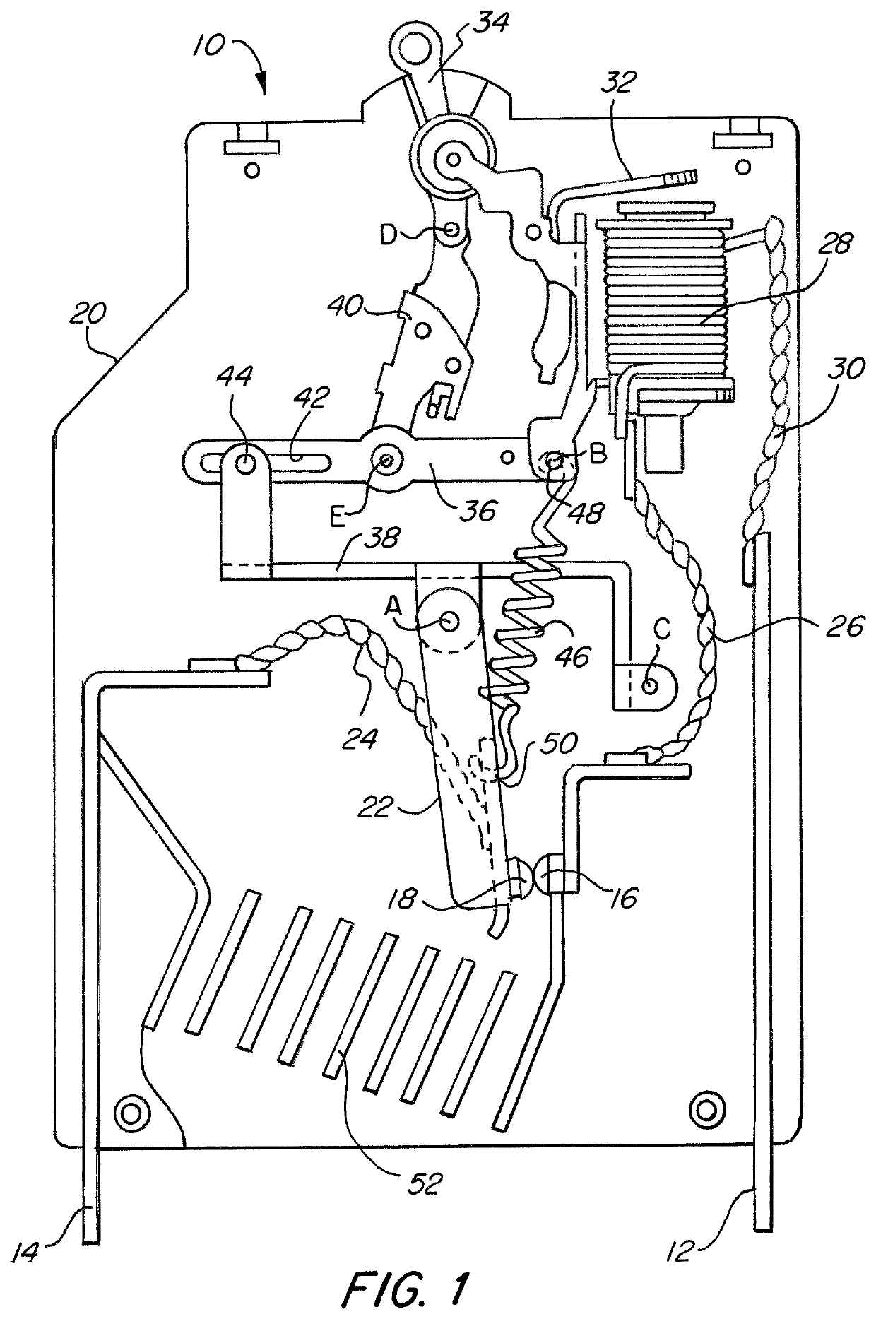
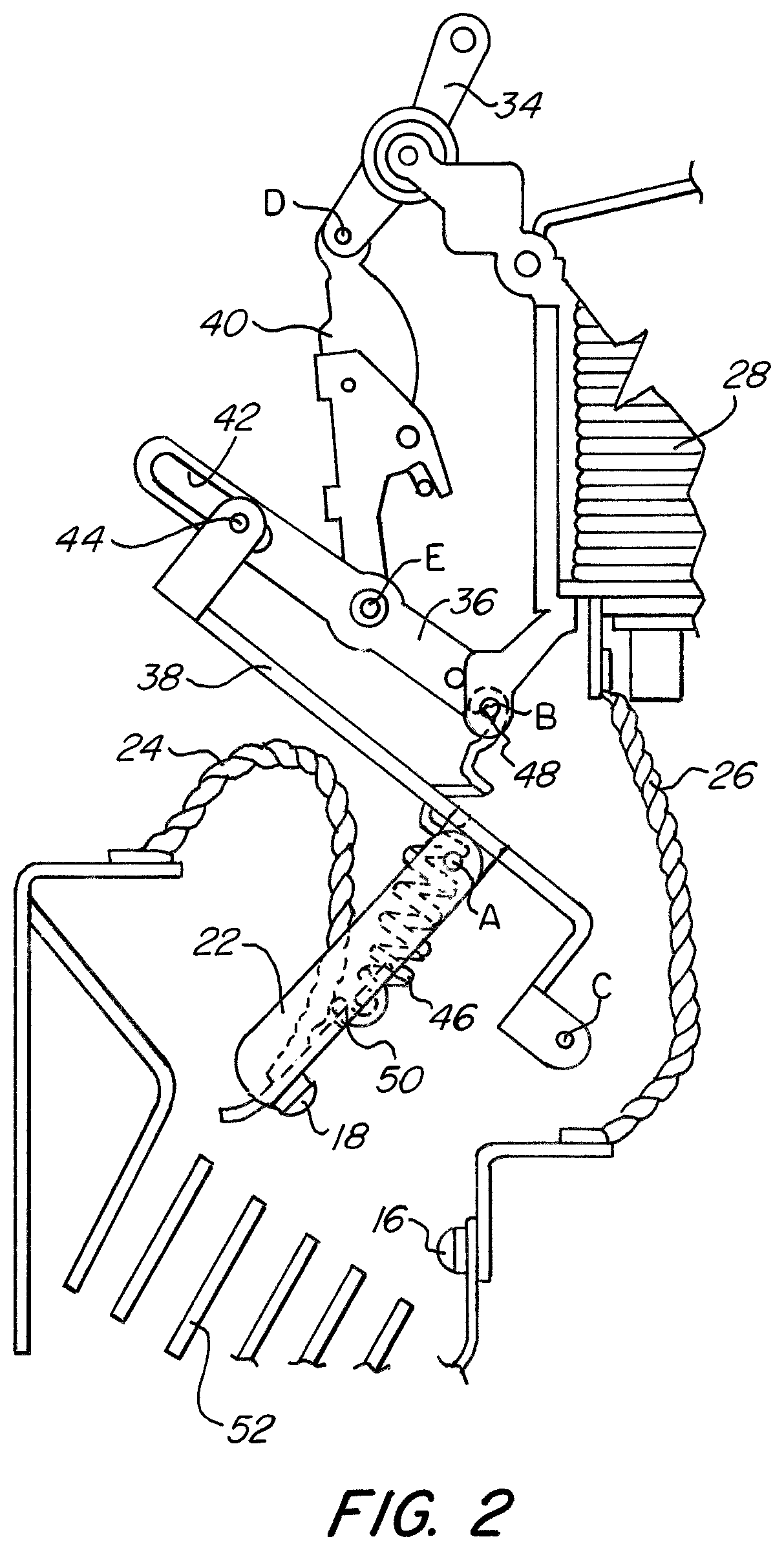
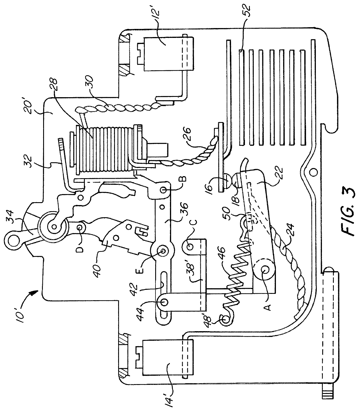
[0031]The exemplary embodiments of the present invention may be further understood with reference to the following description and the related appended drawings, wherein like elements are provided with the same reference numerals.

[0032]The exemplary embodiments of the present invention are related to circuit interrupting devices capable of opening an electrical circuit rapidly and forcefully in the event of a fault or overcurrent condition or in the case that an actuation “off” is commanded. Similarly, the interrupting devices of the exemplary embodiments are also capable of closing an electrical circuit rapidly in the event of resetting a tripped breaker or in the case that a manual actuation “on” is desired. Thereby, the magnitude and / or duration of any arcs created between the opening and / or closing contacts can be kept relatively low, and good physical and electrical contact can be ensured when the contacts are closed.

[0033]More specifically, two exemplary embodiments of the inv...


PUM


Abstract

A circuit interrupter includes a stationary contact and a moveable contact disposed on a moveable contact arm, the moveable contact being configured to be pivotable into and out of physical contact with the stationary contact by pivoting of the moveable contact arm about an axis. The moveable contact arm defines a pivot angle with respect to the stationary contact as the moveable contact arm pivots about the axis. A biasing member exerts a biasing force on the moveable contact arm which pivotally biases the moveable contact toward the stationary contact when the pivot angle is less than a zero-bias angle and which pivotally biases the moveable contact away from the stationary contact when the pivot angle is greater than a zero-bias angle.

Description

FIELD OF THE INVENTION[0001]The present invention relates generally to the protection of electrical devices, and more specifically, relates to a circuit interrupter with snap action contacts, which provide increased speed and reliability when the contacts of the circuit interrupter are being opened and / or closed.BACKGROUND OF THE INVENTION[0002]A circuit interrupter is an electrical component that can break an electrical circuit, interrupting the current. A basic example of a circuit interrupter is a switch, which generally consists of two electrical contacts in one of two states; either closed meaning the contacts are physically touching and electrical current passes from one contact to the other, or open, meaning the contacts are separated relative to each other, thereby preventing the flow of electrical current therebetween. A switch may be directly manipulated by a person as a control signal to a system, such as a computer keyboard button, or to control power flow in a circuit, ...

Claims


Application Information

Patent Timeline
Patent Type & Authority Patents(United States)
IPC IPC(8): H01H9/34H01H71/02H01H73/18H01H83/20H01H1/22H01H71/10
CPCH01H71/0264H01H83/20H01H73/18H01H9/34H01H2205/034H01H71/1009H01H2001/223H01H73/04H01H3/38H01H5/08H01H71/505H01H2071/507H01H2300/046
Inventor FASANO, MICHAEL
Owner CARLING TECH
Why Eureka
Try Eureka