

Spatial filtering in interferometry
a technology of spatial filtering and interferometer, which is applied in the field of interferometers, can solve the problems of large size of trace width, high precision displacement measurement requirements of integrated circuit micro-lithography fabrication, and high cyclic error of higher order, so as to reduce beam shear and associated non-cyclic errors, the effect of reducing the magnitude of beam shear
- Summary
- Abstract
- Description
- Claims
- Application Information
AI Technical Summary
Benefits of technology
Problems solved by technology
Method used
Image

Examples
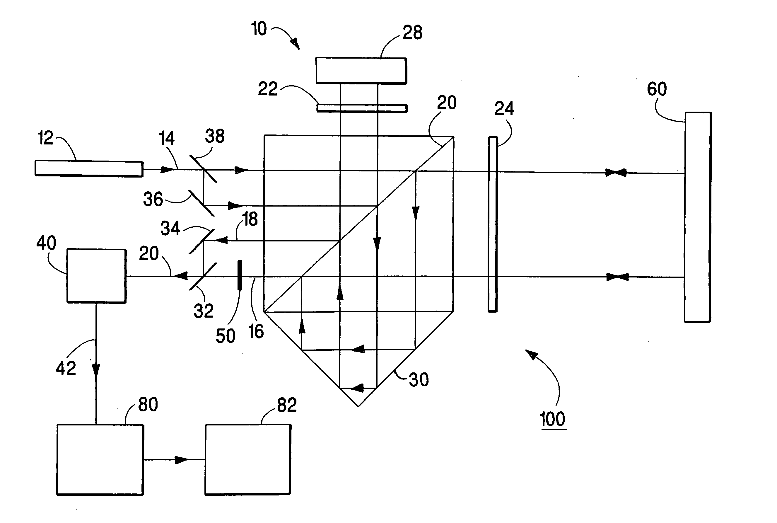
first embodiment
Beam shears b1,ξ and b1,η for the first embodiment are the beam shears that would be exhibited at detector 40 if spatial filter 50 were removed and are
b1,ξ=4L1θ1,ξ, (7)
b1,η=4L1θ1,η, (8)
where θ1,ξ, and θ1,η are the changes in orientation of plane mirror 60 in the plane and orthogonal to the plane, respectively, of FIG. 1.
The amplitude A1,m,T (ξ,η) of the measurement beam transmitted by spatial filter 50 is given by the product of Equations (4) and (6) as A1,m,T(ξ,η)=T1 / 2 (ξ,η) A1,m (ξ,η)(9) =A0 exp{-[ξ-(uB,F2uB2)b1,ξ]2(1uB,F)2-(uB,FuF)2(b1,ξuB)2-[η-(vB,F2vB2)b1,η]2(1vB,F)2-(vB,FvF)2(b1,ηvB)2+ⅈφ12} where 1uB,F2=1uB2+1uF2,(10)1vB,F2=1vB2+1vF2,(11)
and φ1 is the value of φ1 for beam shears b1,ξ and b1,η.
The output measurement beam of beam 20 exhibits an important property. It is evident from Equation (9) that the beam shears b1,ξ,T and b1,η,T of the measurement beam of beam 20 are reduced relative to the corresponding beam shears of the measurement beam of beam...
second embodiment
Beam shears b2,ξ and b2,η for the second embodiment are the beam shears that would be exhibited at detector 140 if spatial filter 150 were removed and are
b2,ξ=4L2θ2,ξ, (25)
b2,η=4L2θ2,η, (26)
where θ2,ξ and θ2,η are changes in orientation of plane mirror 160 in the plane and orthogonal to the plane, respectively, of FIG. 3.
It is evident from Equation (24) that beam shears b2,ξ,T and b2,η,T of output beam 120 are reduced relative to the corresponding beam shears of components of beam 116 according to the formulae b2,ξ,T=uB,F2uB2b2,ξ,(27)b2,η,T=vB,F2vB2b2,η.(28)
The amplitude A2,H of electrical interference signal 142 is obtained by integrating the product of amplitudes A2,r,T and A2,m,T over the ξ and η coordinates wherein the amplitudes are given by Equations (23) and (24). The resulting expression for A2,H is A2,H=A2,H,0(2u2B,2FuB)(2v2B,2FvB)×exp[-(u2B,2FuB,2F)2(b2,ξuB)2-(v2B,2FvB,2F)2(b2,ηvB)2]where(29)1uB,2F2=1uB2+2uF2,(30)1vB,2F2=1vB2+2vF2,(31)1u2B...
PUM
 Abstract
Description
Claims
Application Information