
Image developing device, process cartridge including image developing device, and image forming device including image developing device

a development device and development process technology, applied in the direction of electrographic process devices, instruments, optics, etc., can solve the problems of uneven surface of toner, difficult to arrange such a suppressive measure for suppressing wear, and clogging of toner, so as to reduce the uneven surface of the developer in the vicinity of the detection unit, the effect of blurring an imag

Active Publication Date: 2014-08-12
RICOH KK
View PDF28 Cites 1 Cited by
  • Summary
  • Abstract
  • Description
  • Claims
  • Application Information

AI Technical Summary

Benefits of technology

[0010]In the embodiment, the developer in the first conveyance path is conveyed along the axis direction of the developer supporting body by the first conveyance member, and the developer is lifted to the second conveyance path through the second communication port. The developer in the second conveyance path is conveyed in the direction opposite to the conveyance direction in the first conveyance path by the second conveyance member, and the developer is dropped and returned to the first conveyance path through the first communication port. In this manner, the developer circulates between the first conveyance path and the second conveyance path. At that time, since the developer tends to accumulate around the detection unit of the developer amount detection unit arranged inside the second conveyance path, the developer surface in the second conveyance path is formed to be slanted so that a height of the developer surface is increased along a direction from an upstream side portion in the developer conveyance direction toward the detection unit of the developer amount detection unit. Therefore, even if a developer having a low fluidity is utilized, unevenness of the surface of the developer in the vicinity of the detection unit can be reduced, in comparison to a conventional configuration in which the developer tends not to accumulate in the vicinity of the detection unit. Thus the developer surface can be formed at a more suitable position depending on the amount of the developer. Hence the developer amount detection unit can detect the developer surface formed at the more suitable position, depending on the amount of the developer.
[0011]According to the embodiment, the developer amount detection unit can detect the developer surface formed at the more suitable position compared to a position in a conventional case, depending on the amount of the developer. Therefore, even if a developer having a low fluidity is utilized so as to respond to a longer life-span, an amount of the developer within the device can be more properly detected. Consequently, an image developing device, a process cartridge which utilizes the image developing device, and an image forming device which utilizes the image developing device can be provided such that blurring of an image and clogging of the toner due to an erroneous detection are prevented, and with which high image quality can be maintained for a long time.

Problems solved by technology

However, as the photosensitive body is downsized in accordance with the downsizing of the device, it is becoming difficult to arrange such a suppressive measure for suppressing the wear.
When the fluidity of the toner is reduced, the surface of the toner tends to be uneven and the surface of the toner tends not to be formed stably at a suitable position corresponding to the amount of the developer.
Consequently, the image may be blurred because of the insufficient amount of the toner, or the clogging of the toner may occur because of the overflow of the toner.
However, in this case, the image developing device tends to be large because the developer reservoir is continuously arranged at the upper portion of the extending unit of the upper developer conveyance member.
Thus such a configuration is not suitable for downsizing of the device.
Therefore, a greater amount of the developer may be required and the cost is increased.
Further, when a developer having a low fluidity is used so as to respond to the longer life-span, an excessive amount of the developer within the developing unit may lead to a breakage of the developer conveyance member that is caused by a torque load, or a destruction of the device that is caused by the clogged toner.

Method used


Image

  • Image developing device, process cartridge including image developing device, and image forming device including image developing device
  • Image developing device, process cartridge including image developing device, and image forming device including image developing device
  • Image developing device, process cartridge including image developing device, and image forming device including image developing device

Examples


first embodiment

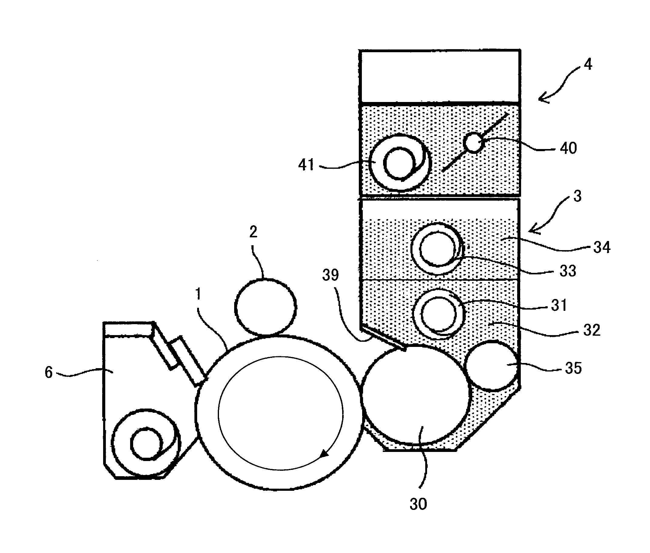
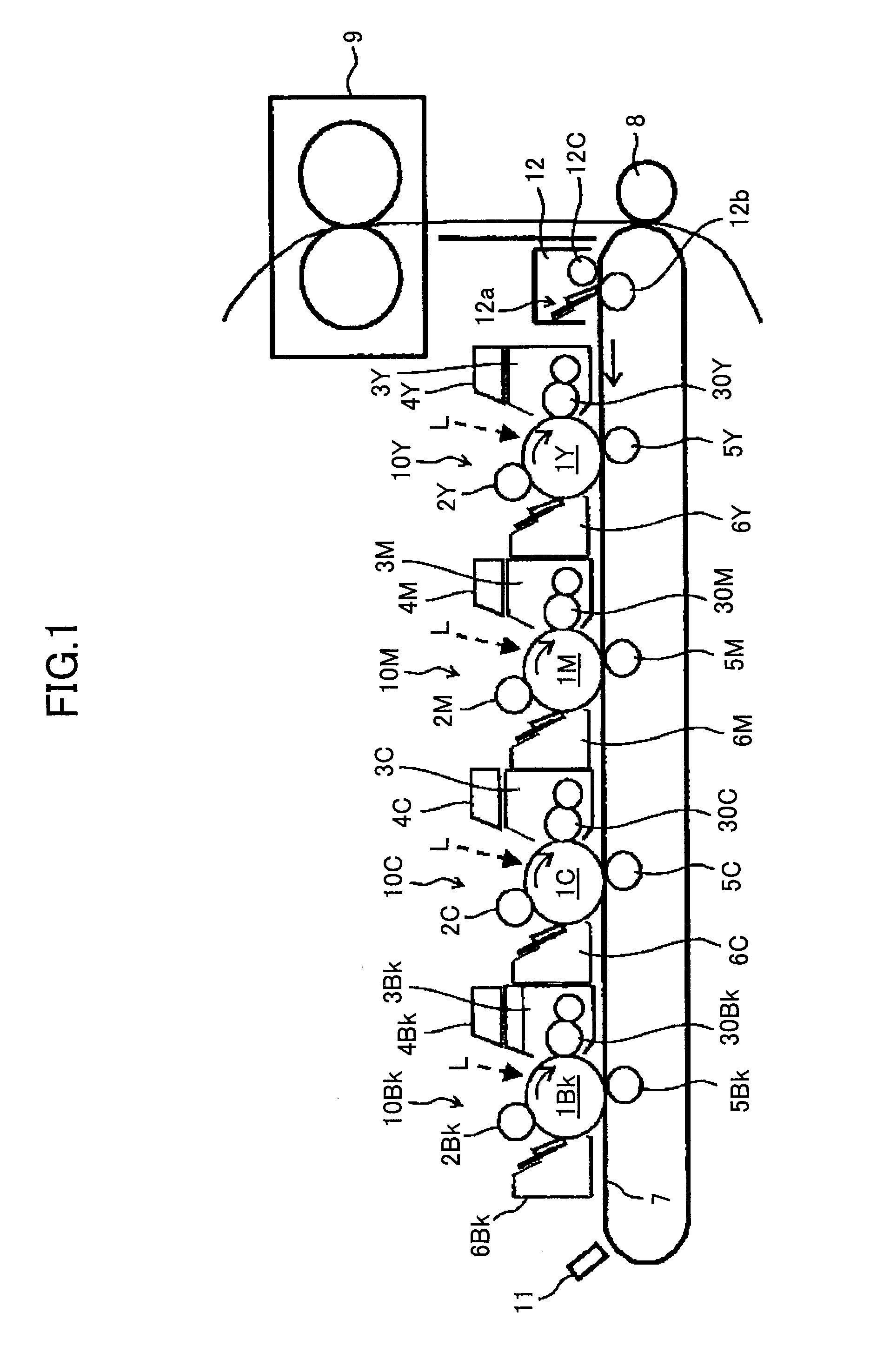
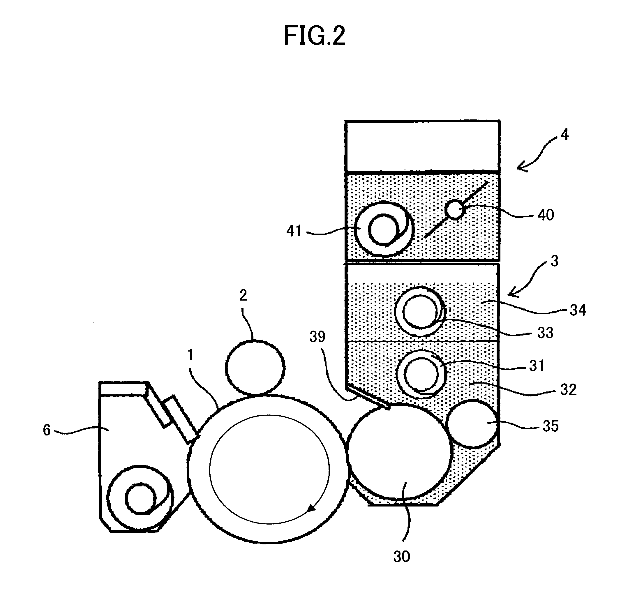
[0065]Hereinafter, an embodiment (referred to as the first embodiment) applied to a color printer, which is an image forming device utilizing an electrographic method, is explained. FIG. 2 is a configuration diagram illustrating configurations of major portions of the printer according to the first embodiment. As shown in FIG. 1, in the printer, four image forming units 10C, 10Y, 10M, and 10Bk, which form a yellow toner image, a magenta toner image, a cyan toner image, and a black toner image, respectively, are arranged in parallel and evenly spaced apart by a predetermined distance along an intermediate transfer belt 7, which is horizontally extended. Hereinafter, the suffixes C, Y, M, Bk indicate colors of cyan, yellow, magenta, and black, respectively. Since the configurations of the four image forming units 10C, 10Y, 10M, and 10Bk are the same except for the colors, the suffixes are sometimes abbreviated in the explanation below. The image forming units 10C, 10Y, 10M, and 10Bk i...

example 1

[0110]In example 1, the toner (1) was used. A screw member having a pitch of 35 mm was used as the upper conveyance member 33 in the upper tank 34. A screw member having a pitch of 25 mm was used as the lower conveyance member 31 in the lower tank 32. The detecting position by the optical sensor 51 was placed above the first communication port 37 of the partition member 36.

example 2

[0111]The same conditions as the conditions of example 1 were applied to example 2, except that the number of the teeth of the screw rotation gear of the upper conveyance member 33 in the upper tank 34 was increased from 45 to 48 and that the rotational speed of the upper conveyance member 33 was increased.


PUM


Abstract

An image developing device includes a developer supporting body; a first conveyance path in which a first conveyance member is arranged; a second conveyance path in which a second conveyance member is arranged; and a partition member that partitions the first conveyance path and the second conveyance path and that has a first communication port and a second communication port. The first communication path and the second communication path communicates with each other through the first communication port and the second communication port. The image developing device includes a developer amount detection unit that includes an optical detection unit arranged in the second conveyance path and that optically detects an amount of the developer in the image forming device. The developer is caused to accumulate in the vicinity of the developer amount detection unit.

Description

TECHNICAL FIELD[0001]Embodiments of the present invention relate to an image developing device that develops a latent image on a latent image supporting body by using a developer supporting body that supports developer, and a process cartridge and an image forming device that utilize the image developing device.BACKGROUND ART[0002]Image forming devices that utilize the electrographic method have been widely used, for example in home offices, or by general users. In order to respond to such utilization in the home offices or by the general users, cost reduction, a longer life-span, downsizing, and stability during operation may be required. In order to realize a longer life-span of an image forming device, wearing of functional materials associated with their use may be minimized. For example, for a photosensitive body, which is an image supporting body, surface wear caused by being contacted by corresponding members in a charging process, a developing process, a transferring process...

Claims


Application Information

Patent Timeline
Patent Type & Authority Patents(United States)
IPC IPC(8): G03G15/08
CPCG03G15/0893G03G15/0862G03G2215/0132G03G15/08
Inventor NAKATAKE, NAOKIKUBOTA, TOMOHIROTSURITANI, SHOHNAGATOMO, YUJIMATSUNO, YASUHIDEKATOH, HIROAKIADACHI, TOMOYAMIYAZAKI, RUMIMIYAZAKI, TAKAFUMIYAMASHITA, TAKESHIABE, KYOKOFUJIWARA, YASUHIROSANADA, TAKAHIRO
Owner RICOH KK
Learn More