System and method for point to multipoint radio survey

a multi-point radio and survey technology, applied in the field of mobile and fixed wireless communications systems, can solve the problems of time-consuming and costly, physical difficulty, and inability to accurately predict the signal level of all radio surveys in real world situations, and achieve the effects of reducing the number of radio surveys

Inactive Publication Date: 2014-08-12
AL SHALASH STEVEN ALI
View PDF11 Cites 4 Cited by
  • Summary
  • Abstract
  • Description
  • Claims
  • Application Information

AI Technical Summary

Problems solved by technology

As can be seen the exact prediction of signal levels from physical principles alone is impractical in real world situations.
However, all these radio surveys are physically much more difficult, time-consuming and costly when compared to predictions.

Method used


Image

  • System and method for point to multipoint radio survey
  • System and method for point to multipoint radio survey
  • System and method for point to multipoint radio survey

Examples


Embodiment Construction

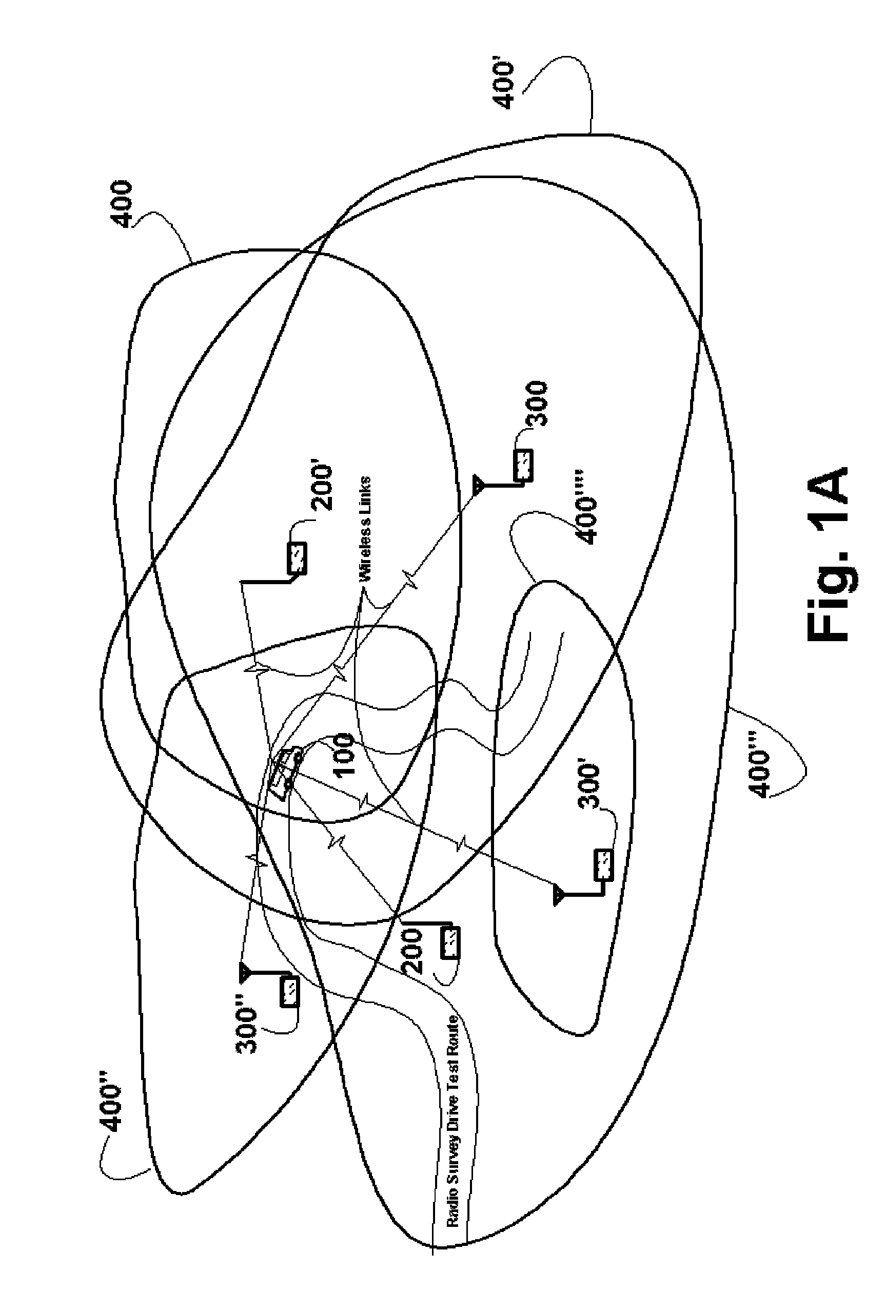
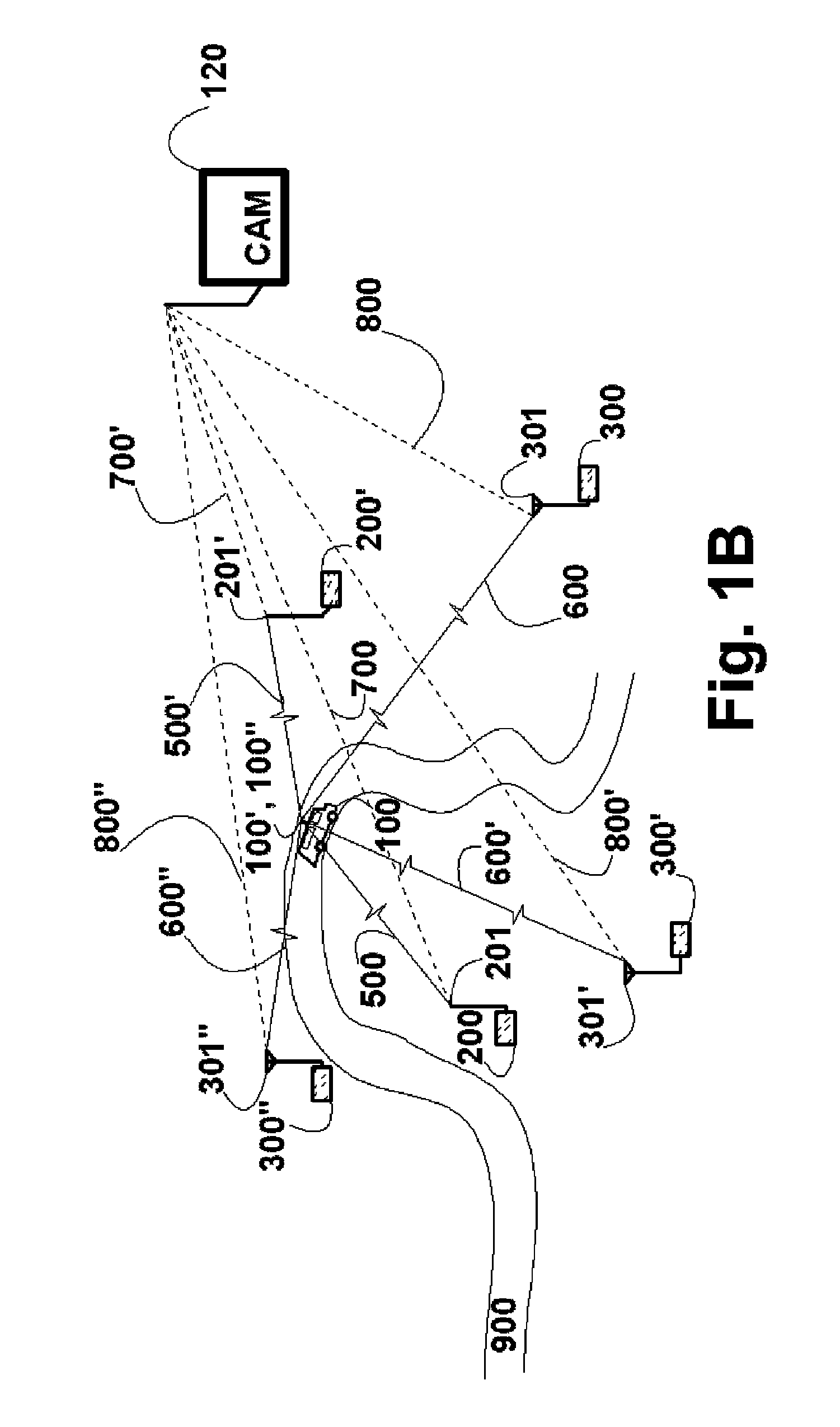
FIGS. 1A and 1B Preferred Embodiments

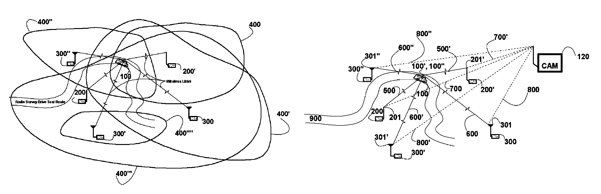
[0070]FIGS. 1A and 1B illustrate radio survey test being preformed on the reverse radio link 500, 500′, 600, 600′, 600″ simultaneously for a plurality of prospective base station candidate sites 200, 200′, 300, 300′, and 300″ at each of which a Stationary Test Receiver 200, 200′, 300, 300′, 300″, etc. (STRX) has been placed. At each of the prospective candidate site's one Stationary Test Receiver 200, 200′, 300, 300′, 300″, etc. (STRX) is connected to a suitable omni-directional 201, 201′, etc. or a sectorized 301, 301′, 301″, etc. receive antenna configuration depending on the survey test requirements for that particular site.

[0071]In this preferred embodiment these Stationary Test Receivers 200, 200′, 300, 300′, 300″, etc. (STRX) sample the signal strength propagating towards them on the reverse radio link 500, 500′, 600, 600′, 600″ at any given moment in time from the Mobile Test Transmitter 101 (MTTX) transported in a suitable drive test vehi...


PUM


Abstract

A methodology and system for performing radio network coverage surveys of multiple site candidates concurrently using one reserved channel based on reverse path signal strength measurements of a signal from a test mobile station transmitter (100) to a plurality of prospective base station receiver sites (200, 200′, . . . ) over a geographical area is presented. The instantaneous position, time-stamp and power of the Transmitter (101) is recorded and stored as it moves along a test route(s). Stationary Test Receiver(s) (201) tuned to the selected channel at each prospective site location (200, 200′, . . . ) save received instantaneous signal strength and, it's time-stamp so they can matched up to the position of the Test Transmitter (101) and used to ascertain received signal strength at each site. Results can be useful for ascertaining optimum site locations, antenna configurations, propagation model tuning, frequency planning, pilot planning and extraction of signal correlation statistics.

Description

FEDERALLY SPONSORED RESEARCH[0001]Not ApplicableSEQUENCE LISTING OF PROGRAMS[0002]Not ApplicableBACKGROUND[0003]1. Field of Invention[0004]This invention generally relates to the field of mobile and fixed wireless communications systems. More particularly the invention pertains to a methodology for performing radio frequency coverage surveys based on actual measurements of radio signal strengths, as propagated over the path from a test mobile station transmitter to one or more test base station receiver points (sites).[0005]2. Description of Prior Art[0006]In designing and implementing new wireless systems for radio communication, or in expanding existent systems, suitable methods are used to select optimal placements of new base station sites that provide for efficient use of the radio frequency spectrum in the given geographical area.[0007]This optimal placement of the base station sites is based on dividing the geographical area under consideration into cells of radio coverage. E...

Claims


Application Information

Patent Timeline
Patent Type & Authority Patents(United States)
IPC IPC(8): H04B7/00H04B7/02H04B17/00
CPCH04W24/10
Inventor AL-SHALASH, STEVEN, ALI
Owner AL SHALASH STEVEN ALI
Why Eureka
Try Eureka