Ocean wave energy harnessing device

a technology of harnessing device and ocean wave energy, which is applied in the direction of sea energy generation, machines/engines, mechanical equipment, etc., can solve the problems of long wavelength wave energy, inefficiency, damage to the pelamis system, etc., and achieves the effect of increasing the efficiency of the salter's duck, increasing the stability of the pelamis system, and extracting a greater amount of energy

a technology of harnessing device and ocean wave energy, which is applied in the direction of sea energy generation, machines/engines, mechanical equipment, etc., can solve the problems of long wavelength wave energy, inefficiency, damage to the pelamis system, etc., and achieves the effect of increasing the efficiency of the salter's duck, increasing the stability of the pelamis system, and extracting a greater amount of energy

US8806865B2Active Publication Date: 2014-08-19FLORIDA INST OF TECH

Image

  • Ocean wave energy harnessing device
  • Ocean wave energy harnessing device
  • Ocean wave energy harnessing device

Examples


Embodiment Construction

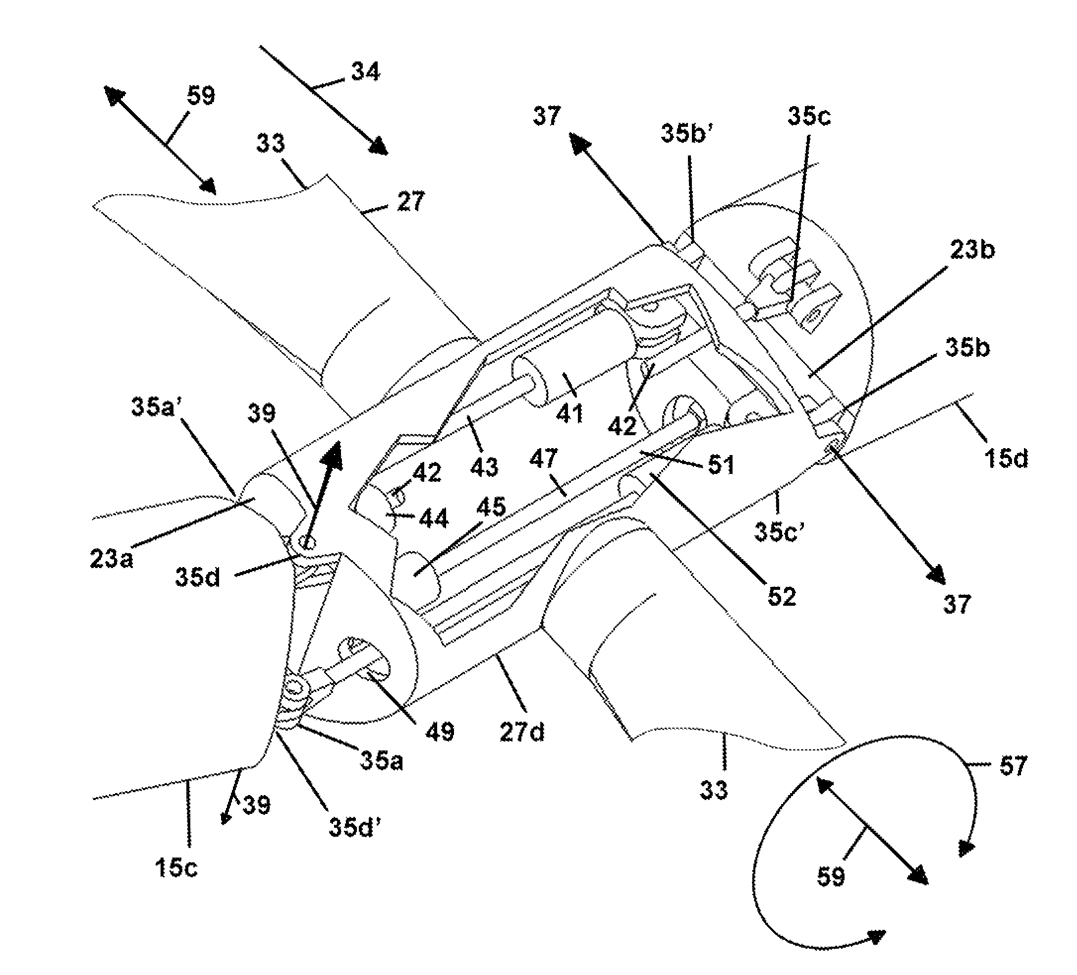
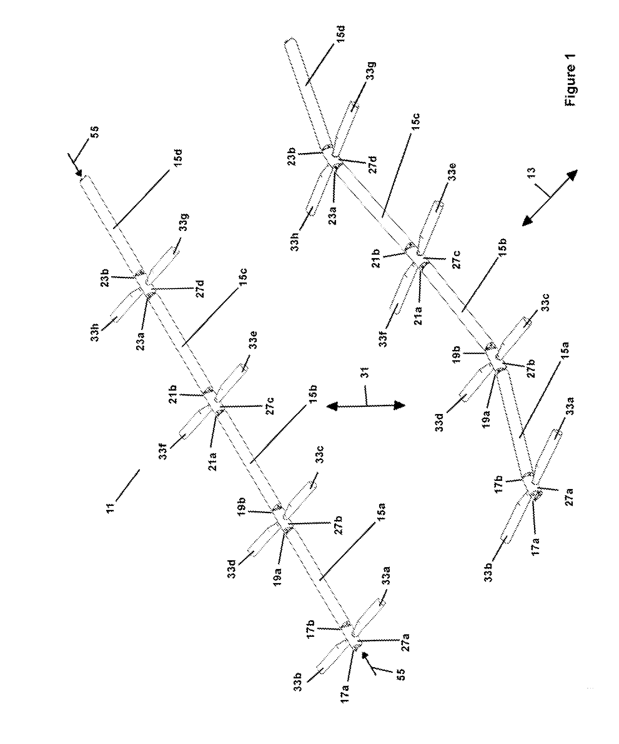
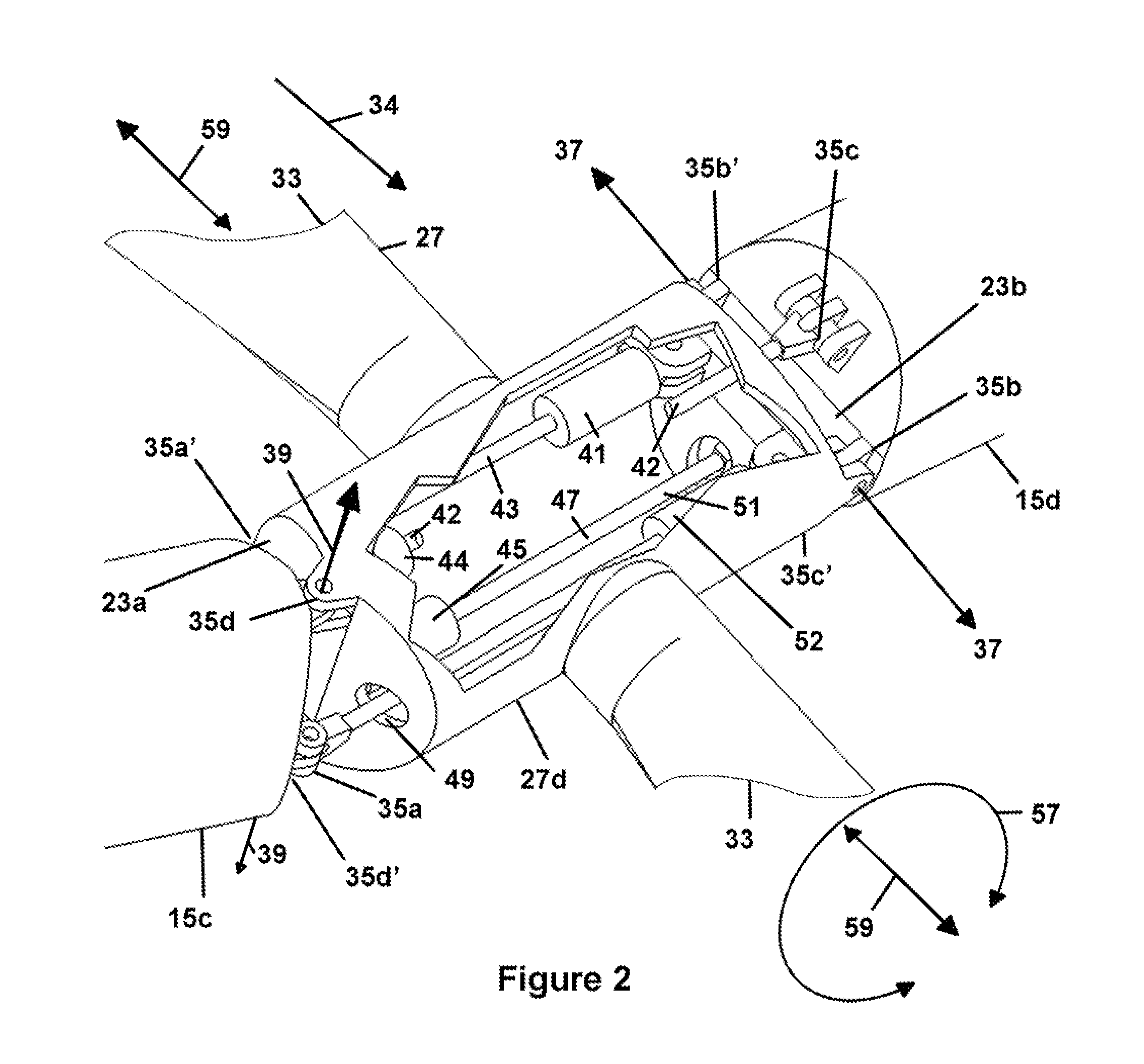
[0034]The Pelamis System as is known and understood by those skilled in the art, is shown in FIG. 1, in two views, at rest generally by numeral 11 and in motion under the force of a transverse wave, shown generally by numeral 13. The moving parts of the Pelamis System are shown by boom elements 15a, 15b, 15c, and 15d, Salter's Duck Pelamis System hinge elements 27a-d and Salter's Duck Blade pairs 33a-b, 33c-d, 33e-f, and 33g-h. As would be known and understood by those skilled in the art, the number of Pelamis system boom elements shown is not restrictive but may be expanded to any suitable number of boom elements, according to the disclosed inventive principles.

[0035]The Pelamis System boom elements 15a-d are linked at respective joints 17a-b, 19a-b, 21a-b, 23a-b, to respective Salter's Duck hinge elements shown by numerals 27a-d, shown with respective blade pairs 33a-b, 33c-d, 33e-f, and 33g-h. As shown, in FIG. 1, joint 17a in Salter's Duck Hinge element 27a is shown without a li...


PUM


Abstract

A system for extracting long wavelength ocean wave energy and for extracting rotational wave energy uses a plurality of boom elements connected to at least one hinge element for movement about the hinge element in a direction of the vertical force of a wave and for movement about the hinge element in a direction of the transverse force of a wave, and the hinge element includes a shaft transverse to the boom elements with a blade mounted to the shaft for rotational movement of the shaft in the direction of the rotational force of a wave.

Description

[0001]A claim for priority is made under 35 U.S.C. 119(e) for provisional patent application No. 61 / 407,507 filed 28 Oct. 2010FIELD OF USE[0002]Transfer of the energy present in ocean waves to electrical or mechanical energy.BACKGROUND OF THE INVENTION[0003]Energy in ocean waves and its extraction by conversion to alternate energy forms, is well known and has been the subject of continuing efforts.[0004]The wave energy exists in two forms, in a traveling wave seen as displacing the ocean in a vertical movement as the wave is seen to move transversely to the vertical movement and in a circular or rotational movement and energy. This traveling wave energy is most noticeable as the wave energy reaches the shore producing “breakers.” It may be seen off shore noticeable a “whitecaps,” where the vertical movement of the ocean in a localized area, as displaced by the wave energy raises the water level relative to its immediate surrounding level, causing the level to collapse, producing the...

Claims


Application Information

Patent Timeline
19 Aug 2014
Publication
US8806865B2
IPC
F03B13/14
CPC
F03B13/20; Y02E10/38; Y02E10/30
Inventors
DUNN, KELLY; HAUSMANN, DERIC