Brake release device attached to a door machine

a technology of a door machine and a release device, which is applied in the direction of safes, alarms with smoke/gas/colored powder, instruments, etc., can solve the problems of high inventory cost, time-consuming and costly development process, etc., and achieve the effect of reducing the development cost extending the application field of the door machine, and simplifying manufacturing

Active Publication Date: 2014-08-19
HSIEH CHUNG HSIEN
View PDF19 Cites 10 Cited by
  • Summary
  • Abstract
  • Description
  • Claims
  • Application Information

AI Technical Summary

Benefits of technology

[0009]In order to achieve above and other objects, the brake release device attached to a door machine according to the present invention mainly comprises: a base plate provided at the exterior of the door machine, and having a horizontal guiding portion provided at one end thereof; a passive plate guided by the guiding portion to slide between a first position and a second position; a guiding member fixed on the base plate and having an axial guiding hole; a sliding pin mounted within the guiding hole for sliding therein, one end of the sliding pin corresponding to a brake release bar and the other end of the sliding pin being connected to the passive plate; a spring element accommodated in the guiding hole, one end of the spring element abutting against the guiding member and the other end of the spring element abutting against the sliding pin in such a manner that the sliding pin is exerted by elastic potential energy to have a tendency to move toward the brake release bar; and a fusible link device provided at a predetermined position, the fusible link device being connected with the sliding pin through a connecting member so as to resist the restoring force of the spring element, so that the sliding pin is maintained at a distance from the brake release bar, and the passive plate is kept at the first position; when the surroundings temperature exceeds a melting point of the fusible link device, the fusible link device melts to release the connecting member connecting the sliding pin, and the sliding pin slides toward the brake release bar under the action of the restoring force of the spring element to impact against the brake release bar so as to release the brake device, causing the sliding-down by the weight of the door slats and simultaneously causing the passive plate to slide to the second position. In this manner, the door machine for ordinary purpose and the door machine for fireproof door can be used in common by employing the brake release device attached to a door machine of the present invention. Not only the application field of the door machine is extended, but also simplification on manufacturing and reduction on development cost of the door machine can be achieved.
[0010]Another object of the present invention is to provide a brake release device attached to a door machine, which can lock a pull chain disc, configured manually to rotate an axle of the door machine, when the brake is released by the brake release device, so as to prevent the pull chain disc from being actuated due to human error in the process of closing the rolling door, which will interrupt the closing of the door.
[0011]According to the present invention, the brake release device attached to a door machine further comprises: a ring plate fixed together with the pull chain disc, the ring plate having a plurality of equally spaced openings formed along the entire circumference thereof; a plurality of plug pins, corresponding to the openings on the ring plate, provided on the end face of the passive plate, when the passive plate is located at a first position, the plug pins are separated from the openings, and when the fusible melt device melts, causing the brake release device to release brake, the passive plate slides to a second position to cause the insertion of the plug pins into the corresponding openings on the ring plate, so that the pull chain disc is unable to be rotated. This can prevent the pull chain disc from being erroneously actuated by personnel in case of fire emergency to cause incomplete shutting of the fireproof door.

Problems solved by technology

Hence, development proceedings are time-consuming and costly.
Further, the manufacturing is complicated due to large number of parts, and thus inventory cost is high.

Method used


Image

  • Brake release device attached to a door machine
  • Brake release device attached to a door machine
  • Brake release device attached to a door machine

Examples


Embodiment Construction

[0018]The technical features of the present invention will be described by the following embodiments in conjunction with the accompanying drawings. However, it is to be noted that this invention is not limited to these embodiments. Further, the direction indicated in this context is only for the convenience of description, not intended to limit to a particular orientation.

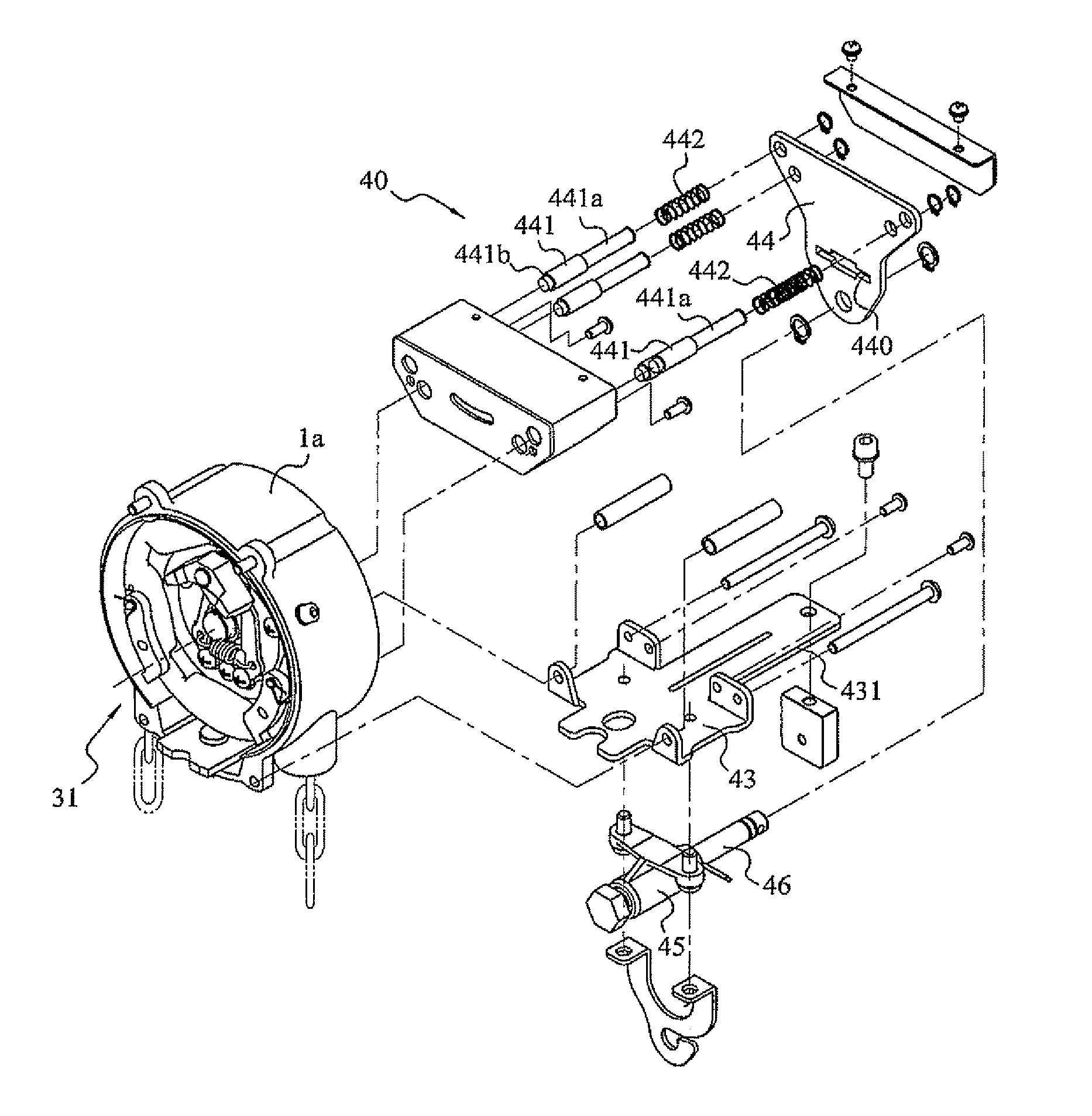
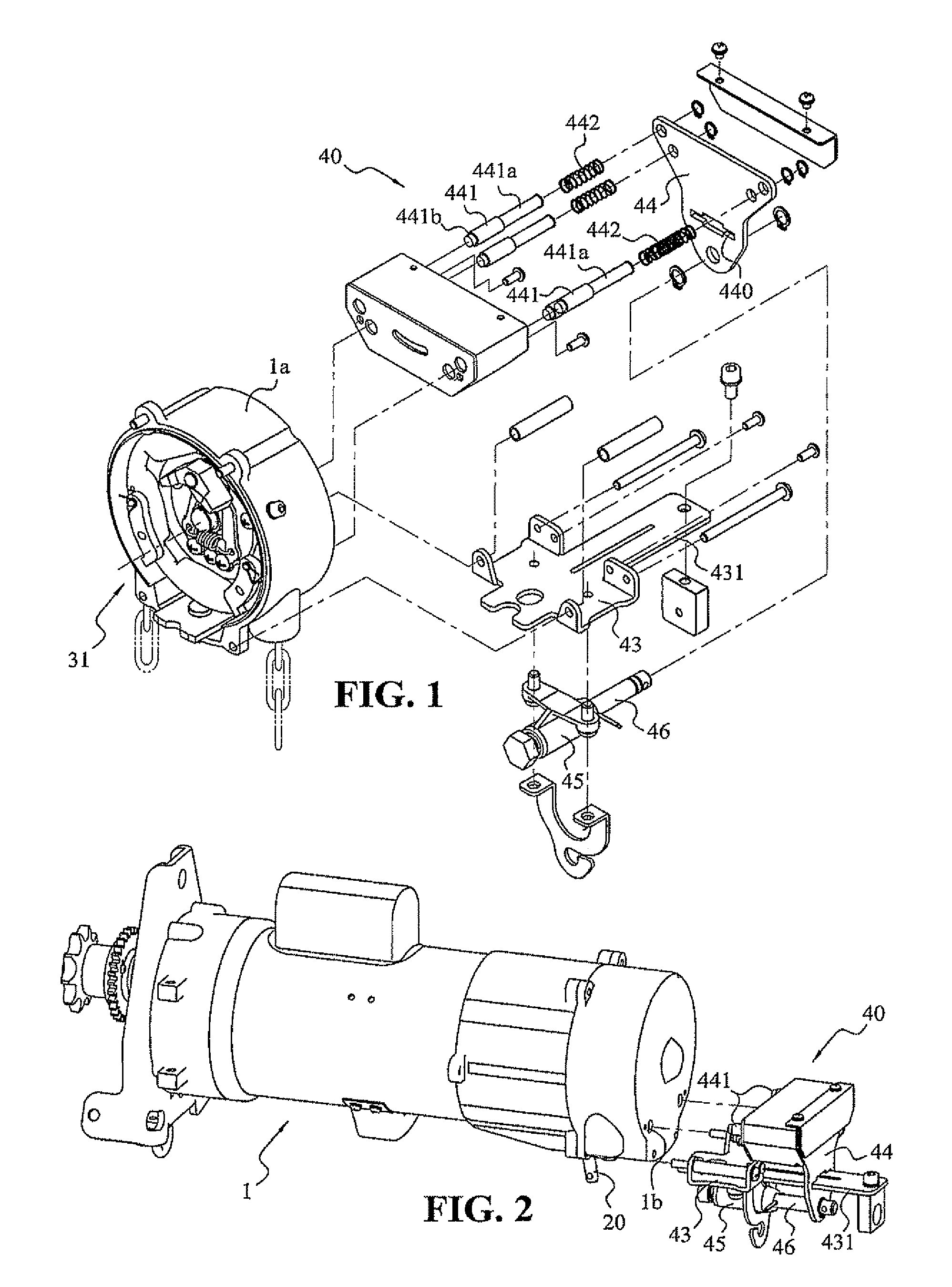
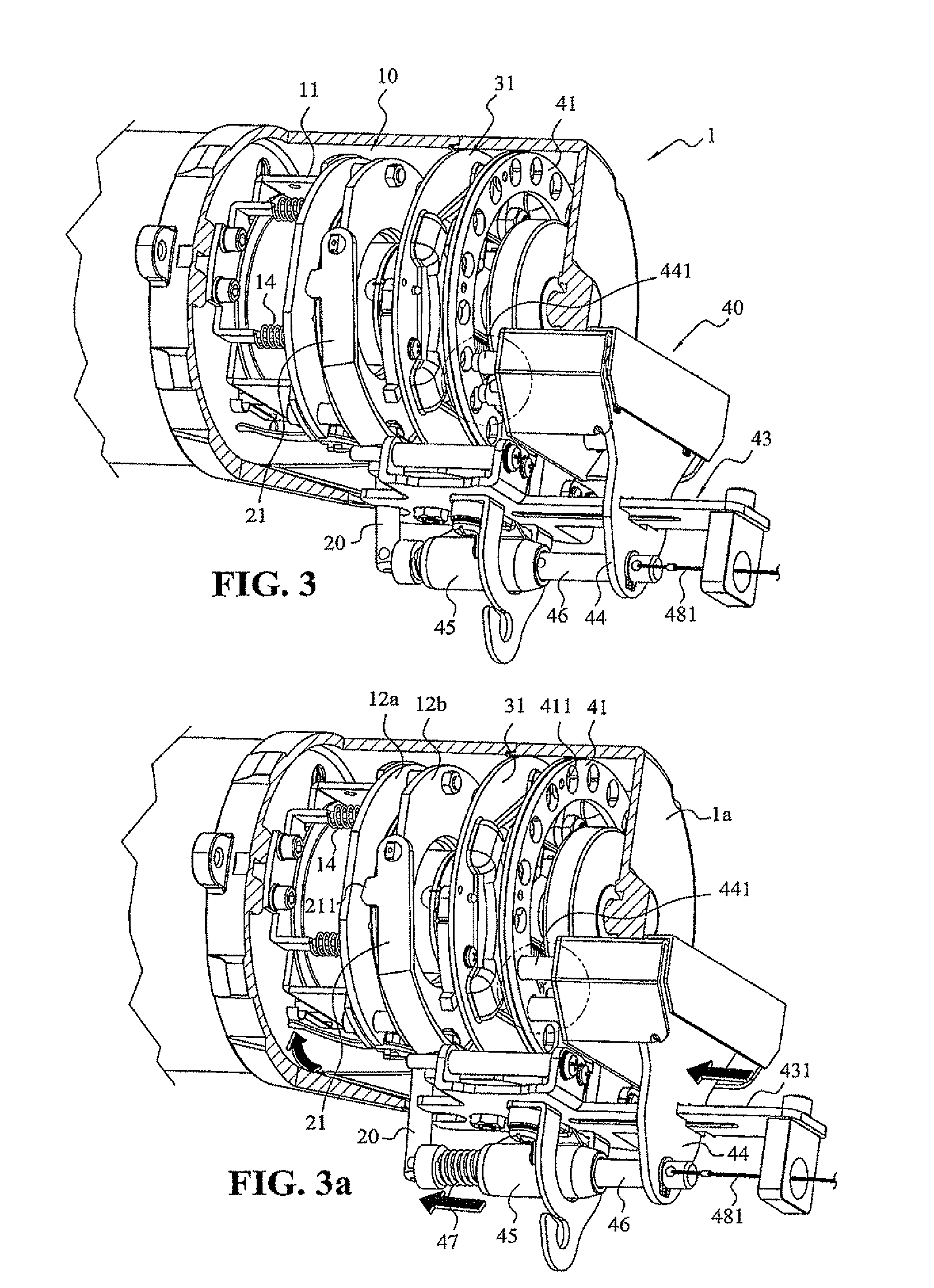
[0019]FIGS. 1 and 2 show a brake release device attached to the exterior of a door machine. FIGS. 3, 3a, 4 and 4a are used to further describe the other objects and effects of the present invention by perspective and sectional views respectively.

[0020]Referring to the drawings, a door machine 1 is of the type that generally employed on a rolling door, a garage door or a safety door that moves vertically. The door machine 1 basically comprises an axle 2; a brake device 10 for braking the axle 2; a brake release bar 20 provided to extend to the outside of the door machine 1 for actuating the brake device 10 so as to ...


PUM


Abstract

A brake release device attached to a door machine comprises a ring plate provided with a plurality of openings and fixed on a pull chain disc, a base plate located at the outside of the door machine, a passive plate provided with a plurality of plug pins that correspond to the openings of the ring plate and slides together with the sliding pin, a guiding member fixed together with the base plate, a sliding pin corresponding to a brake release bar for releasing brake of the door machine and slidably guided by the guiding member, a spring element and a fusible link device that curbs the sliding pin from leaving the brake release bar. By the spring element, the guiding member stores potential energy for sliding.

Description

BACKGROUND OF INVENTION[0001]1. Field of the Invention[0002]This invention relates to a brake release device for a door machine, more particularly to a brake release device attached to an ordinary door machine in such a manner that the door machine is promoted a function as a door machine for a fireproof door.[0003]2. Background Art[0004]A door machine that is generally employed, for example, in a vertically lifted rolling door or a garage door, comprises at least a brake device for braking the door machine so as to maintain the rolling door or the door slats at a specified or a stationary position. This type of brake device, for example, is described in U.S. Pat. No. 7,341,129 granted to the Applicant, which mainly comprises a support frame having a plurality of guiding bars; a first braking pad guided by the guiding bars so as to be movable in an axial direction of the door machine axle; a second braking pad provided at the end portion of the guiding bars; a braking component incl...

Claims


Application Information

Patent Timeline
Patent Type & Authority Patents(United States)
IPC IPC(8): F16D63/00F16D59/02B62C7/02F16D65/28
CPCF16D2055/0058F16D63/00F16D65/28F16D55/28F16D2127/04F16D2121/22F16D59/02
Inventor HSIEH, CHUNG-HSIEN
Owner HSIEH CHUNG HSIEN
Why Eureka
Try Eureka