
Helicopter with oblique tail boom

a technology of oblique tail boom and helicopter, which is applied in the field of helicopters, can solve the problems of negative or downward lift, limited maximum pitch angle on the retreating blade side, and even the needless loss of tail rotors, so as to reduce the cross-sectional area

Inactive Publication Date: 2014-08-19
DEUTSCHES ZENTRUM FUER LUFT & RAUMFAHRT EV
View PDF34 Cites 11 Cited by
  • Summary
  • Abstract
  • Description
  • Claims
  • Application Information

AI Technical Summary

Benefits of technology

Enables high-speed flight by selectively generating lift on the retreating blade side and reducing mechanical loads on short wings, while providing effective counter torque to the horizontal rotor, stabilizing the helicopter in autorotation and allowing for efficient forward thrust.

Problems solved by technology

In the inner area of the horizontal rotor, where the circumferential velocities of the rotor blades are lower, even reverse flow may occur at the rotor blades, which result in a negative or downward lift.
Further, the shroud of the tail rotor reduces the danger of colliding with its rotating rotor blades which are hardly visible to people approaching the landed helicopter.
In forward flight of a helicopter, the tail rotor may be assisted by a fin at the end of the tail, and the tail rotor may even become needless due to this fin.
Nevertheless, the different flow velocities on the advancing blade and the retreating blade side of the horizontal rotor mark a limit for the velocity reachable with a helicopter in forward flight as the maximum pitch angle on the retreating blade side is limited by the danger of a flow separation with a simultaneous breakdown of the lift.
Further, this airflow is not homogeneous, but it comprises vortices and even shockwaves which cause considerable accelerations of the short wings in different directions.

Method used


Image

  • Helicopter with oblique tail boom
  • Helicopter with oblique tail boom
  • Helicopter with oblique tail boom

Examples


Embodiment Construction

[0030]The term “vertical longitudinal middle plane” as used here refers a virtual vertical plane longitudinally dividing the fuselage of the helicopter in halves of similar shape.

[0031]The terms “horizontal rotor” and “vertical rotor” as used here, do not necessarily mean that the respective rotor exactly extends or runs in a horizontal or vertical plane, or that the respective rotor axis is exactly oriented vertically or horizontally. In a helicopter, for example, it is usual to provide at least a part of its forward drive by tilting the rotor axis of its horizontal rotor in forward direction.

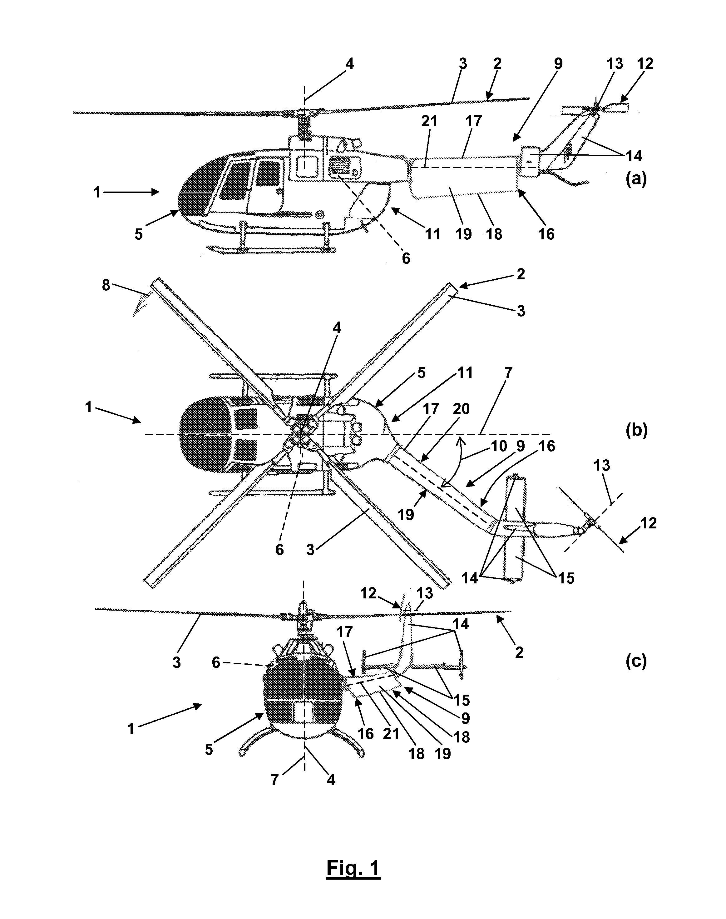
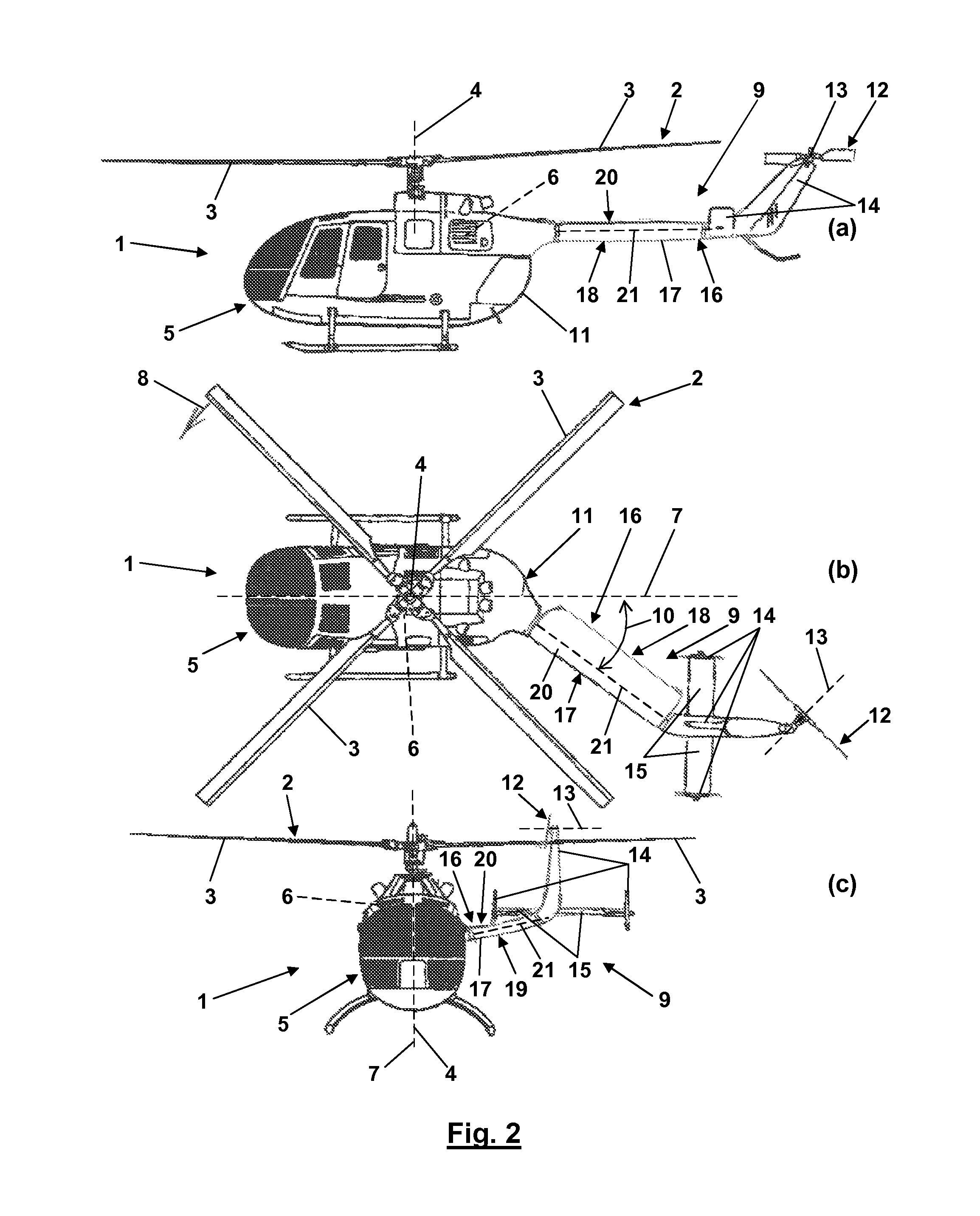
[0032]The tail of a helicopter according to the present invention is asymmetric, i.e. particularly not mirror symmetric with regard to the vertical longitudinal middle plane of the helicopter. It may be that a helicopter according to the present invention has an additional boom at the advancing blade side of the horizontal rotor in a similar position as the tail on the retreating blade side of...


PUM


Abstract

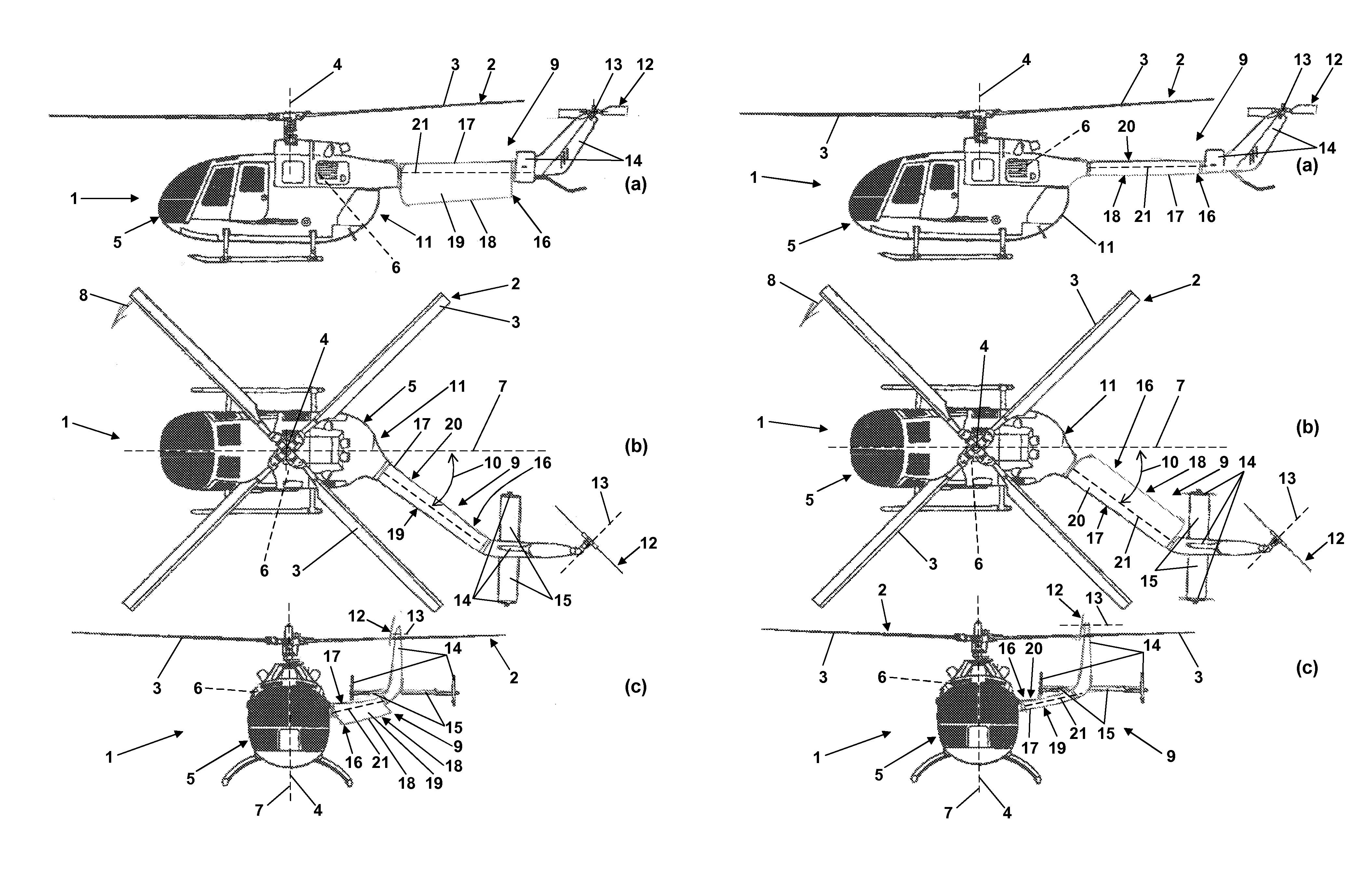
A helicopter (1) has a horizontal rotor (2) driven for rotation about a vertical rotor axis (4), and a tail (9) extending backwards from the rotor axis (4) at a fixed angle (10) between about 20° and about 60° to a vertical longitudinal middle plane (7) of the helicopter (1) on a retreating blade side of the horizontal rotor (2). The tail (9) comprises a profiled body (16) including aerodynamic effective surfaces (19, 20) for selectively generating lift on the retreating blade side of the horizontal rotor (2) in forward flight of the helicopter (1). For hovering flight of the helicopter (1), the profiled body (16) can be swiveled about a swivel axis running parallelly to the main axis (21) of the tail for reducing a cross-sectional area of the profiled body facing the horizontal rotor (2).

Description

CROSS REFERENCE TO RELATED APPLICATIONS[0001]This application claims priority to co-pending German Patent Application No. DE 10 2012 100 102.2 entitled “Hubschrauberkonfiguration”, filed Jan. 6, 2012.FIELD OF THE INVENTION[0002]The present invention relates to a helicopter comprising a horizontal rotor driven for rotation about a vertical rotor axis and a boom extending away from the rotor axis.BACKGROUND OF THE INVENTION[0003]On helicopters, two aspects have to be particularly cared for. On the one hand, a counter torque has to be provided to the torque of the horizontal rotor driven for rotation about the vertical rotor axis. Without such a counter torque the fuselage of the helicopter would rotate about the vertical rotor axis in opposite direction to the horizontal rotor.[0004]On the other hand, in forward flight of a helicopter, due to the rotational movement of the horizontal rotor, the flow against the rotor blades on the advancing blade side of the horizontal rotor strongly ...

Claims


Application Information

Patent Timeline
Patent Type & Authority Patents(United States)
IPC IPC(8): B64C27/82B64C5/10B64C27/04
CPCB64C27/04B64C5/10B64C39/029
Inventor RAFFEL, MARKUSRICHTER, KAIGARDNER, ANTHONY
Owner DEUTSCHES ZENTRUM FUER LUFT & RAUMFAHRT EV
Learn More