Stochastic Time-Digital Converter

a converter and time-digital technology, applied in the field of time-digital converters, can solve the problems of indeterminacy of comparator judgment, severe deviation, and limited improvement of resolution, so as to reduce the influence of process, supply voltage and temperature (pvt) on the circuit, and reduce the cost of hardware, power consumption, and area

Inactive Publication Date: 2014-08-19
SOUTHEAST UNIV
View PDF15 Cites 2 Cited by
  • Summary
  • Abstract
  • Description
  • Claims
  • Application Information

AI Technical Summary

Benefits of technology

[0014]In the present invention, an input switching circuit is added at the input terminal of the STDC to switch the rising edges of two input signals in alternate and drive the STDC, so that the two input signals are connected to the input terminal of the comparator in alternate; as a result, the influences of component mismatch, process, supply voltage, and temperature (PVT) on the circuit are minimized; in addition, the stochastic behavior of the comparators are fully utilized, so that the number of equivalent comparators in the STDC is doubled. To attain the same resolution, the number of used comparators in the STDC is halved, and thereby the hardware cost, power consumption, and area are also halved.

Problems solved by technology

The resolution of a TDC with such a structure is equal to the delay time in each stage of delayer, and therefore highly depends on the manufacturing technology; meanwhile, the deviation is severe, and further improvement of resolution is limited.
In case the phases of two signals are close to each other, the judgment of the comparator may have indeterminacy, owing to the influence of PVT and mismatch of components.
However, since the achievable resolution is directly related with the number of used comparators, a large number of comparators are required to improve the resolution; as a result, the power consumption, area and hardware cost will be inevitably increased.

Method used


Image

  • Stochastic Time-Digital Converter
  • Stochastic Time-Digital Converter
  • Stochastic Time-Digital Converter

Examples


Embodiment Construction

[0021]Hereunder the technical scheme of the present invention will be further detailed, with reference to the accompanying drawings.

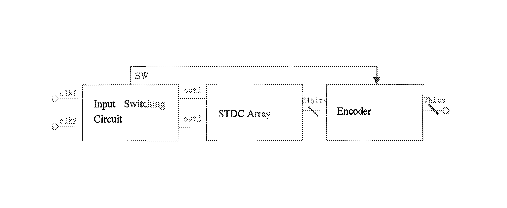
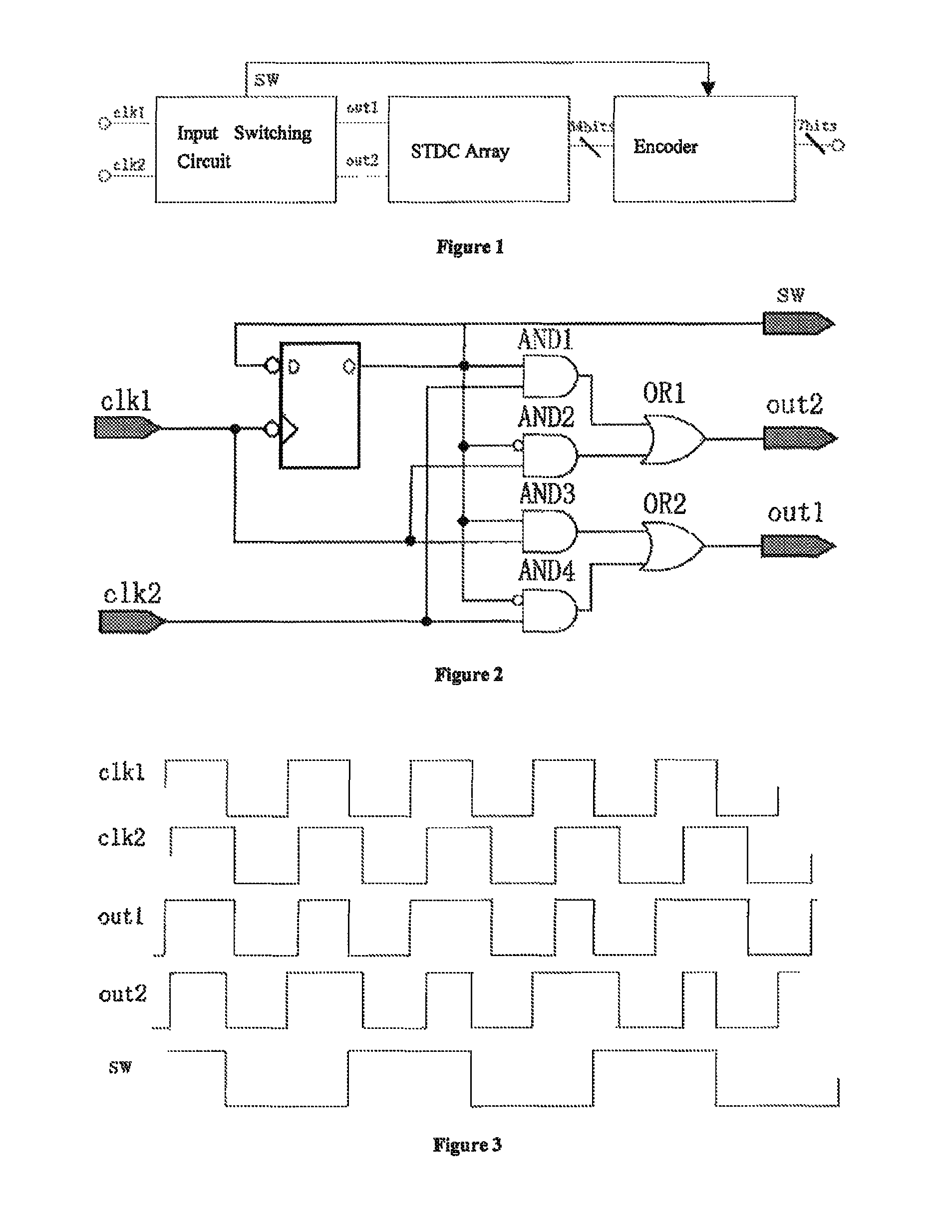
[0022]As shown in FIG. 1, the STDC comprises an input switching circuit, an STDC array, and an encoder, wherein, the input switching circuit is implemented with a digital logic circuit, the STDC array is composed of 64 identical comparator units, and the encoder is a 64-7 encoder controlled by sw signal. Two clock input signals clk1 and clk2 are connected to the input terminals of the input switching circuit, the outputs out1 and out2 of the input switching circuit are connected to the input terminal of each comparator in the STDC array respectively, the output signal sw is connected to the encoder and serves as a control signal, which is a frequency-halving signal triggered by the falling edge of clk1. The 64-bit judgment result produced by STDC is connected to the encoder, which generates a 7-bit output.

[0023]As shown in FIG. 2, the input switching ci...


PUM


Abstract

A stochastic time-digital converter (STDC) including an input switching circuit, an STDC array, and an encoder. A clock circuit inputs two clock signals into two input terminals of the input switching circuit; the input switching circuit transmits the two clock signals in a cyclic cross-transposition form to two input terminals of the STDC array, and simultaneously outputs a trigger control signal to the encoder; each comparator in the STDC array independently judges the speeds of the two clock signals and sends the judgement results to the encoder for collection and processing; and the encoder outputs the size and positivity or negativity of the phase difference of the two clock signals. The technical solution utilizes the stochastic characteristic of the STDC to double the number of the equivalent comparators in the STDC array, eliminating the effects on the circuitry of device mismatching and processes, power supply voltage, and temperature.

Description

PRIORITY CLAIM[0001]The present application is a National Phase entry of PCT Application No. PCT / CN2012 / 076202, filed May 29, 2012, which claims priority from Chinese Application Number 201110191203.X, filed Jul. 8, 2011, the disclosures of which are hereby incorporated by reference herein in their entirety.FIELD OF THE INVENTION[0002]The present invention relates to a stochastic time-digital converter that contains an input switching circuit and can discriminate the time difference between the rising edges of two clock signals and present the time difference in a digital form.BACKGROUND OF THE INVENTION[0003]A Time-Digital Converter (TDC) is widely applied in integrated circuits and mainly used to provide phase discrimination for a digital phase-locked loop (DPLL). In addition, in many application scenarios, such as nuclear medicine imaging, laser ranging, and half life testing of particles in high energy physics, etc., a TDC is used to discriminate minute time (phase) differences....

Claims


Application Information

Patent Timeline
Patent Type & Authority Patents(United States)
IPC IPC(8): H03M1/04G04F10/00
CPCH03M1/04G04F10/005
Inventor WU, JIANHUIWANG, ZIXUANSHI, XIAOZHANG, MENGHUANG, CHENGCHEN, CHAOHUANG, FUQINGJI, XINCUNJIANG, PING
Owner SOUTHEAST UNIV
Why Eureka
Try Eureka