
Flat-tubular solid oxide cell stack

a solid oxide cell and stack technology, applied in the field of flat-tubular solid oxide cell stacks, can solve the problems of low power density (output), difficult to greatly increase the size, and change the temperature and concentration of the first gas at the inlet end and the outlet end, so as to reduce the stress of cell stacking, reduce the stress of sealing portions, and increase the efficiency of electrical energy generation

Active Publication Date: 2013-10-10
KOREA INST OF ENERGY RES
View PDF4 Cites 2 Cited by
  • Summary
  • Abstract
  • Description
  • Claims
  • Application Information

AI Technical Summary

Benefits of technology

The present invention solves problems with previous designs by providing a flat-tubular solid oxide cell stack that minimizes stress, sealing, and changes in chemical reactions. This results in increased efficiency when used as a fuel cell and purer gas when used as a high-temperature electrolyzer.

Problems solved by technology

The flat type electrochemistry reaction device has an advantage of high power density (output) but is disadvantageous in that the area of a portion to be sealed for gas is comparatively large, there is a thermal shock that occurs because of the difference in coefficients of expansion between components when stacked, and it is difficult to greatly increase the size thereof.
However, the cylindrical type is disadvantageous in that power density (output) is low.
However, such devices have a problem in that, when cells are stacked to minimize the sealing area and a first gas that flows in the stacked cells flows through a first gas flow channel in a zigzag manner, the temperature and concentration of the first gas at the inlet end and the outlet end change, and thus efficient electricity generation cannot be achieved.

Method used


Image

  • Flat-tubular solid oxide cell stack
  • Flat-tubular solid oxide cell stack
  • Flat-tubular solid oxide cell stack

Examples


example 1

Manufacture of Cell Stack

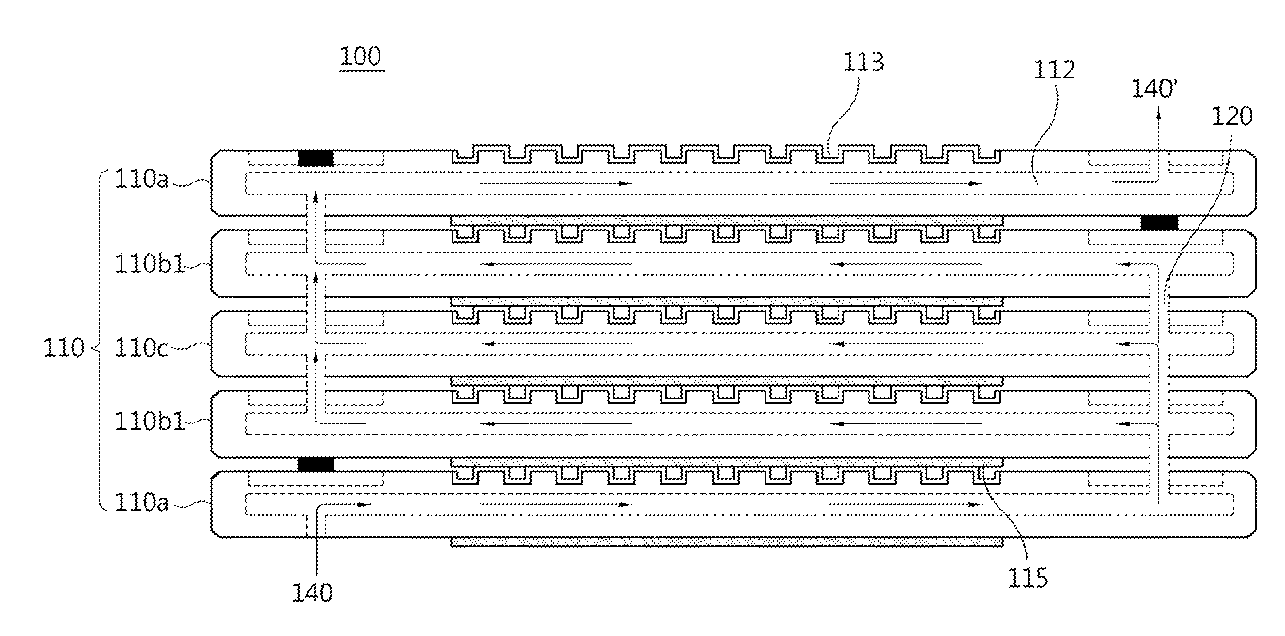
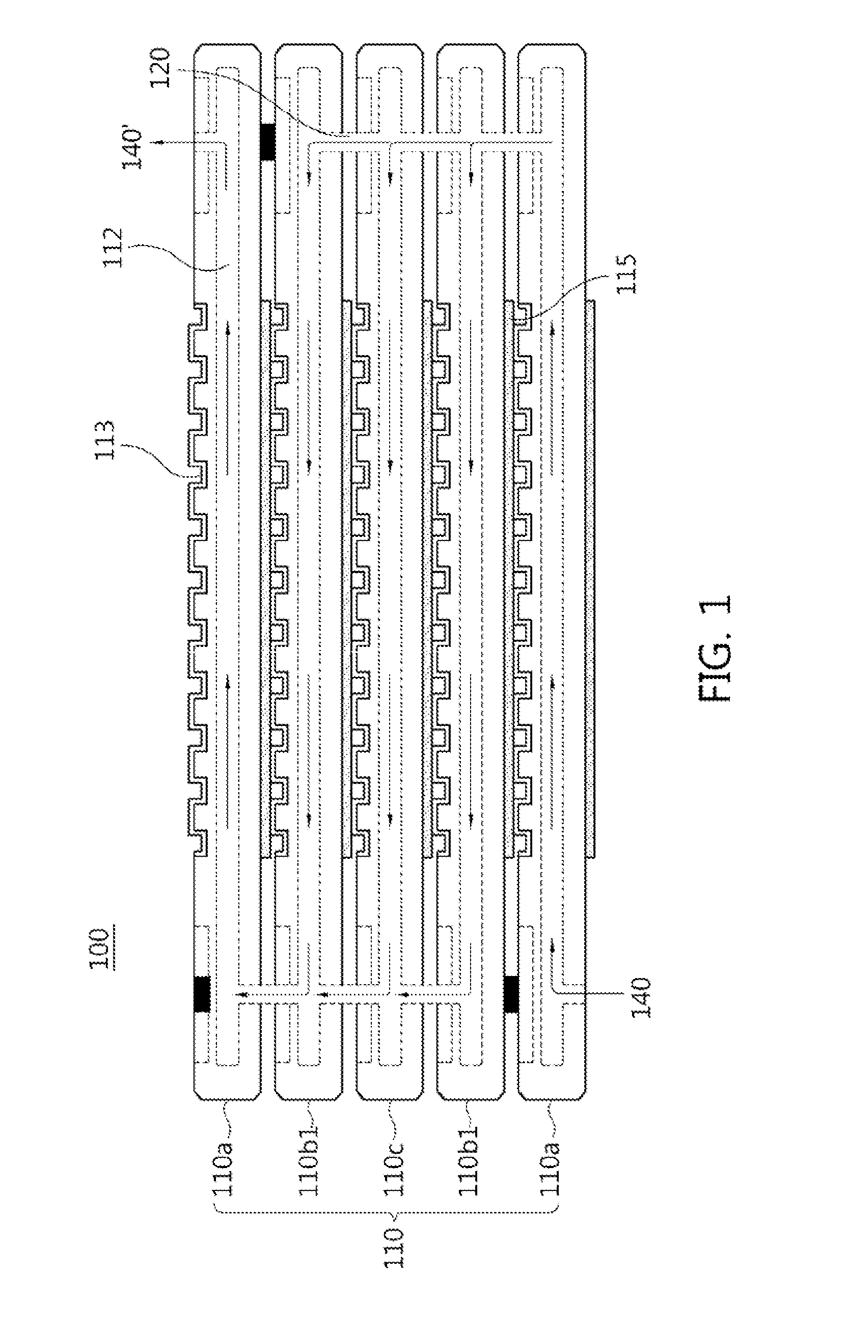
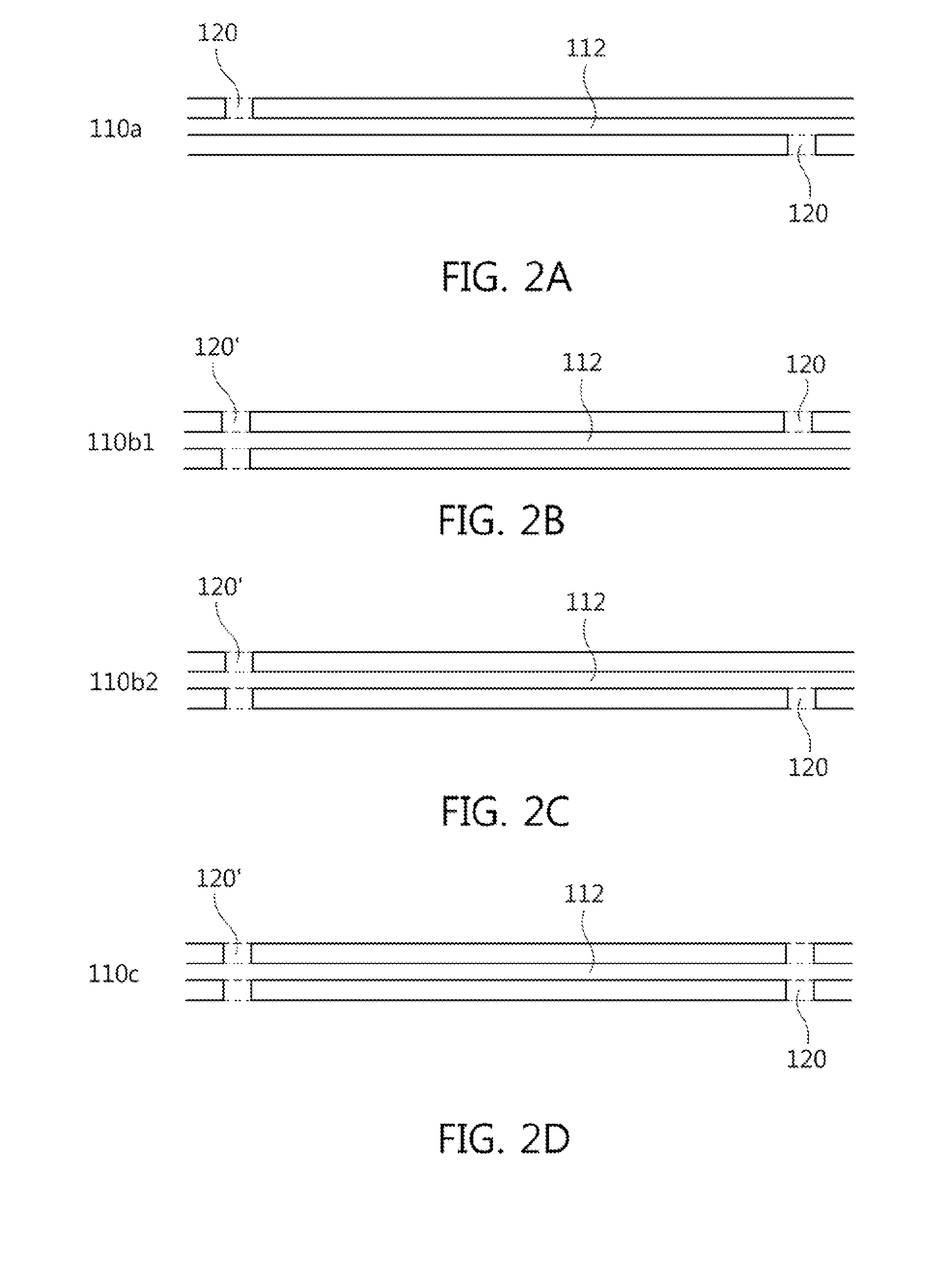
[0045]Using a ceramic extrusion molding machine, an anode was molded such that a first-gas flow channel was formed therein, and both ends thereof were sealed. Then, connection holes for connecting the first-gas flow channels of unit cells to each other were formed at portions near both ends of the dried molded body in the thickness direction of the cells. As a result, the following unit cells were manufactured: a unit cell 110a in which the connection holes passing through both sides of the cell, respectively, are formed in directions opposite to each other so as to be connected with the first-gas flow channels of the cells adjacent thereto; unit cells (110b1 and 110b2) in which a connection hole passing through both sides of the cell is formed at a portion near one end of the cell in the thickness direction of the cell, and a connection hole passing through any one side of the cell is formed at a portion near the other end of the cell in the thickness direc...


PUM


Abstract

Disclosed herein is a flat-tubular solid oxide cell stack in which the pathway of chemical reactions is long and the temperature and flow rate of feed gas are maintained at uniform levels, thus the efficiency of electrical energy generation is increased when the cell stack is used as a fuel cell, and the purity of generated gas (hydrogen) is increased when the cell stack is used as a high-temperature electrolyzer.

Description

CROSS-REFERENCE TO RELATED APPLICATION[0001]This application claims priority to Korean Patent Application No. KR 10-2012-0035868, filed on Apr. 6, 2012, which is incorporated herein by reference in its entirety.BACKGROUND OF THE INVENTION[0002]1. Field of the Invention[0003]Exemplary embodiments of the present invention relate to a flat-tubular solid oxide cell stack, and more particularly to a flat-tubular solid oxide cell stack in which the pathway of chemical reactions is long and the changes in the temperature and flow rate of feed gas are minimized, and thus the efficiency of electrical energy generation is increased when the cell stack is used as a fuel cell, and the purity of generated gas (hydrogen) is increased when the cell stack is used as a high-temperature electrolyzer.[0004]2. Description of Related Art[0005]Generally, fuel cells use high-efficiency clean electricity generation technology in which oxygen in the air and hydrogen contained in a hydrocarbon material, such...

Claims


Application Information

Patent Timeline
IPC IPC(8): H01M8/04
CPCH01M8/04089H01M8/04007H01M8/243Y02E60/50H01M8/2483H01M8/02H01M8/12H01M8/24
Inventor SEO, DOO-WONKIM, SUN-DONGHAN, IN-SUBYU, JI-HAENGKIM, SE-YOUNGWOO, SANG-KUK
Owner KOREA INST OF ENERGY RES
Learn More