Beam shaping of RF feed energy for reflector-based antennas

a technology of reflector-based antennas and beam shaping, which is applied in the direction of antennas, simultaneous aerial operations, electrical equipment, etc., can solve the problems of increasing the central blockage of the rf feed pattern and further increasing the size of the central blockag

Active Publication Date: 2014-08-19
RAYTHEON CO
View PDF14 Cites 175 Cited by
  • Summary
  • Abstract
  • Description
  • Claims
  • Application Information

AI Technical Summary

Benefits of technology

[0011]In another embodiment, an antenna feed is located approximately at the focal point of a primary reflector for illuminating the primary reflector with or receiving from the primary reflector radio frequency (RF) energy of a predefined RF wavelength. A sensor receives or transmits energy of a second predefined wavelength different from the predefined RF wavelength. A secondary reflector is positioned with its forward surface facing the primary reflector and the sensor and its rear surface facing the antenna feed. A selective coating on the forward surface allows transmission of RF energy at the predefined RF wavelength there through and reflects energy of the second predefined wavelength. An RF beam-shaping element is formed on the rear surface of the secondary reflector. The element may, for example, comprise a conical section, printed phase plate or dielectric gradient. The RF beam-shaping element is configured to direct RF energy from the feed away from a blockage created by the feed, secondary reflector and sensor towards unblocked regions of the primary reflector.

Problems solved by technology

The IR optical system may increase the central blockage of the RF feed pattern.
This laser spot tracker may further increase the size of the central blockage.

Method used


Image

  • Beam shaping of RF feed energy for reflector-based antennas
  • Beam shaping of RF feed energy for reflector-based antennas
  • Beam shaping of RF feed energy for reflector-based antennas

Examples


Embodiment Construction

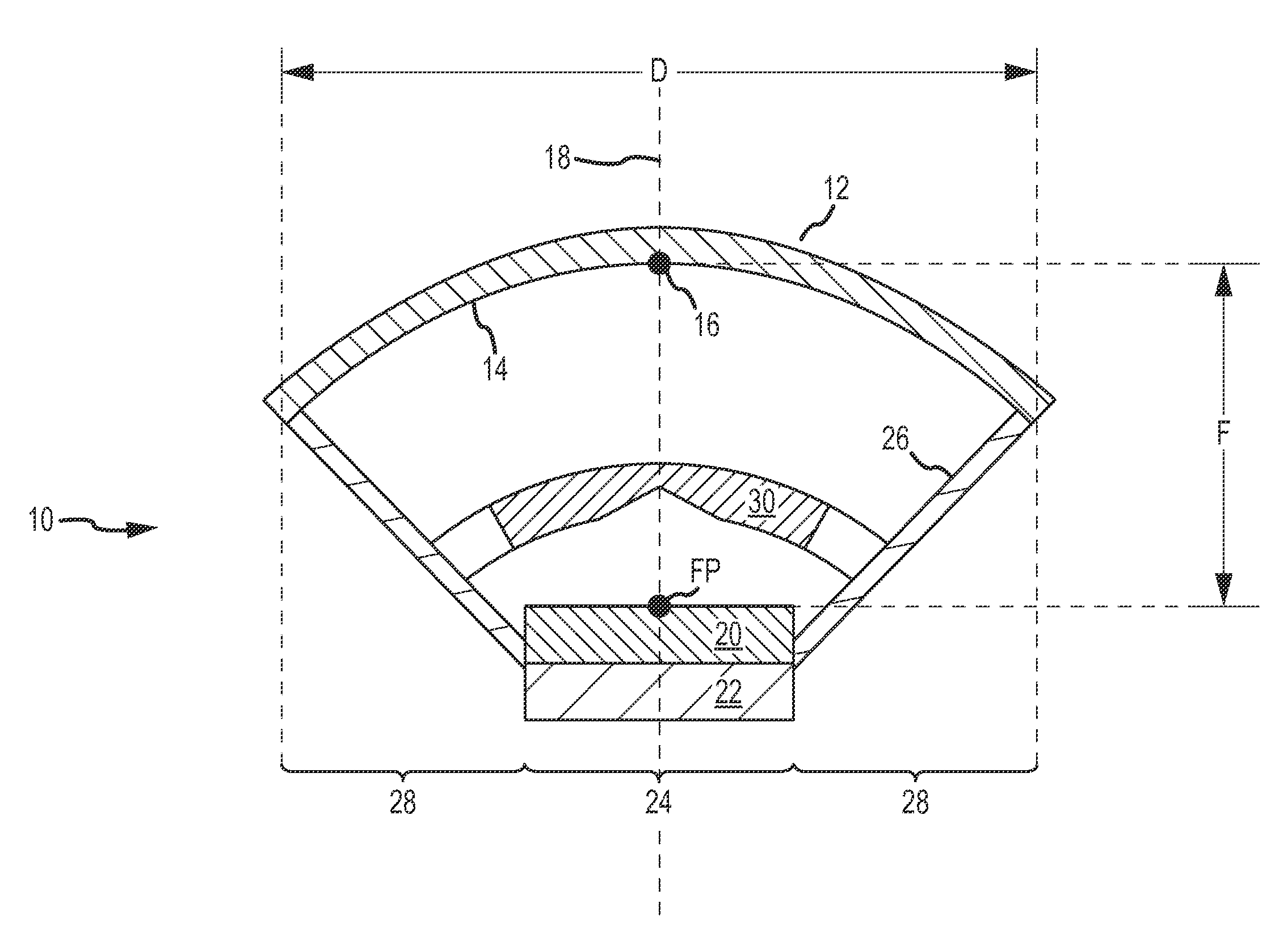
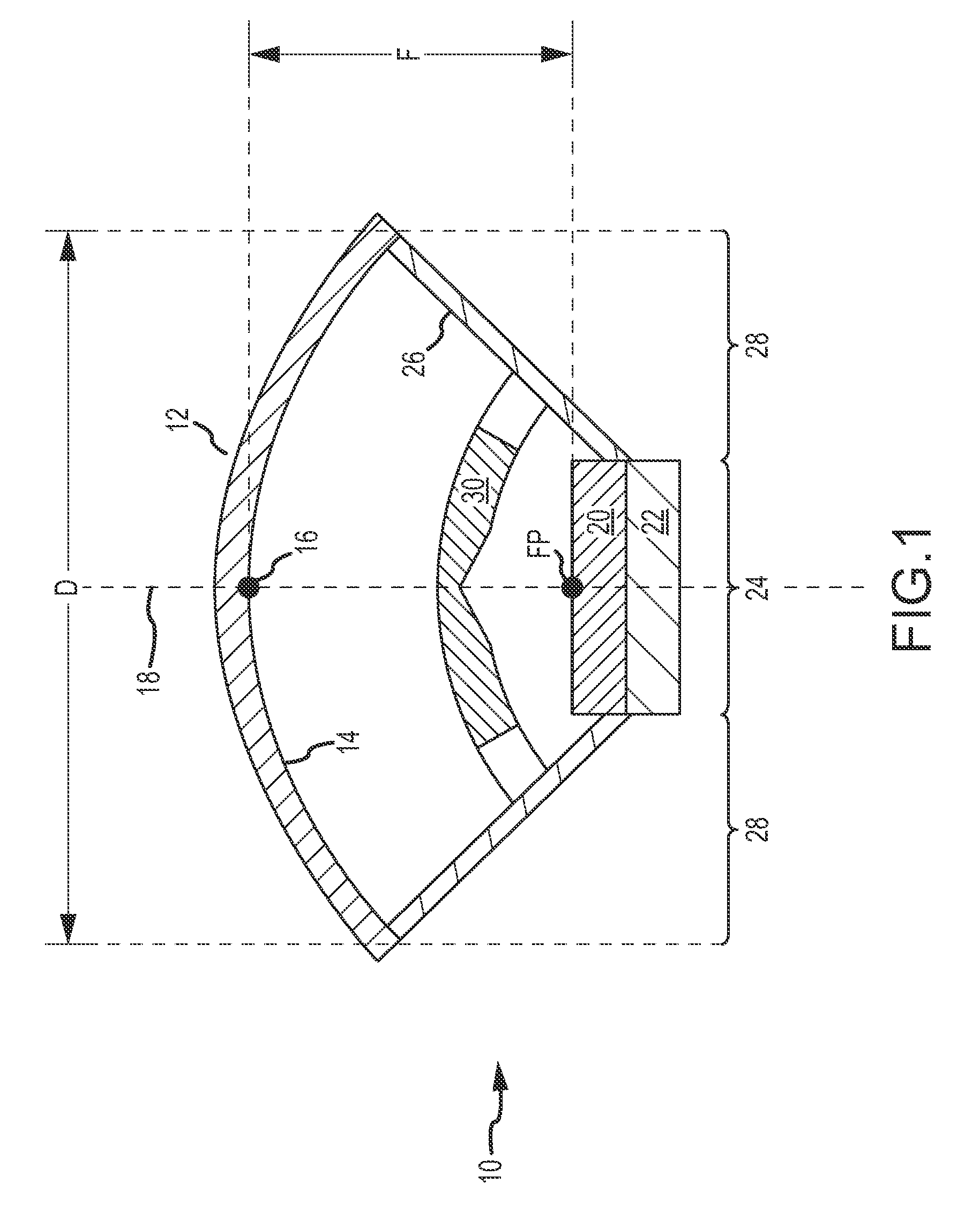
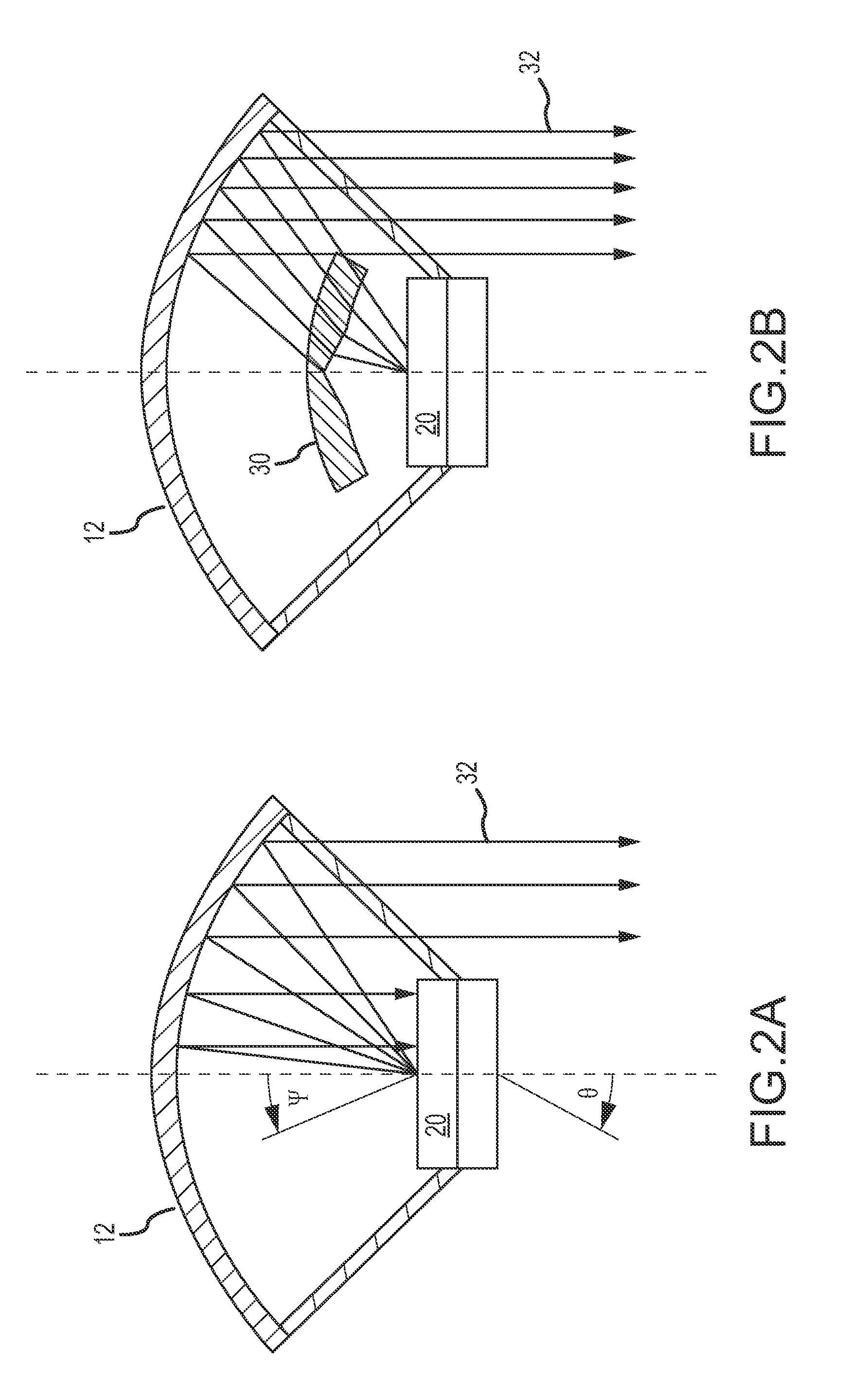
[0021]The invention describes beam shaping of RF feed energy for reflector-based antennas. A RF beam-shaping element is located between the primary reflector and the antenna feed. The RF beam-shaping element is configured to direct RF energy from the feed away from a blockage created by the feed itself towards unblocked regions of the primary reflector outside the blockage. Inclusion of the beam-shaping element allows for a simplified feed design. The feed may comprise fewer feed elements, each comprising a radiating element and an unexposed or straight feed to the radiating element. The feed design may be simplified such that the feed illuminates the primary reflector such that in the absence of the beam-shaping element a maximum power density is radiated toward the blockage of the reflector and tapers to a lower power density in the unblocked regions. The beam-shaping element reshapes the illumination such that the power radiated toward the blockage is reduced and the majority of ...


PUM


Abstract

A beam-shaping element is provided to shape RF feed energy for reflector-based antennas. The RF beam-shaping element is located between the primary reflector and the antenna feed and configured to direct RF energy from the feed away from a blockage created by the feed itself towards unblocked regions of the primary reflector. The beam-shaping element allows for a simplified feed design. The feed may comprise one or more feed elements, each comprising a radiating element and a feed to the radiating element such as a cavity-backed slot radiator and stripline trace. In a monopulse tracking system, each quadrant may include only a single feed element. In common aperture systems, the RF beam-shaping element may be formed on only the rear surface of the secondary reflector that allows transmission at the predefined RF wavelength while reflecting energy of a second predetermined wavelength to another sensor.

Description

BACKGROUND OF THE INVENTION[0001]1. Field of the Invention[0002]This invention relates to reflector-based antennas, and more particularly to beam shaping of RF feed energy for reflector-based antennas including, but not limited to, single, dual and tri-mode sensors for target tracking.[0003]2. Description of the Related Art[0004]The basic design and operation of reflector-based antennas are well known and well documented in technical literature. In the simplest configuration, one or more RF feed elements are located near the focal point of a reflective surface (e.g. a parabolic dish). The reflective surface acts to collect incoming electromagnetic energy from a distant source in the far field in a particular direction to the feed element(s) in the focal area and / or re-radiate energy from the feed element(s) in a directive fashion towards the same particular direction into the far field. Reflector antennas are used for satellite communication, radio astronomy, target tracking, and ma...

Claims


Application Information

Patent Timeline
Patent Type & Authority Patents(United States)
IPC IPC(8): H01Q19/12H01Q19/02H01Q19/06H01Q19/19
CPCH01Q19/027H01Q19/12H01Q19/19H01Q19/062H01Q15/08H01Q15/0013H01Q15/23H01Q5/22
Inventor CANNON, BENJAMIN L.TAYLOR, BYRON B.
Owner RAYTHEON CO
Why Eureka
Try Eureka