Spring-biased floor-mounted door hinge

a technology of floor-mounted door hinges and hinges, which is applied in the direction of hinges, wing accessories, manufacturing tools, etc., can solve the problems of high cost and complex installation of hydraulic springs of the state of art, and achieve the effects of low cost, small size and complex installation

Active Publication Date: 2014-08-26
BOSTON INNOVATION GATEWAY LLC +13
View PDF31 Cites 6 Cited by
  • Summary
  • Abstract
  • Description
  • Claims
  • Application Information

AI Technical Summary

Benefits of technology

[0006]Thus, one object of this present application is for an elastomeric spring for door closures that replaces the conventional hydraulic springs, providing a mechanical assembly of small size and requires a small hole on the floor for fitting.
[0007]One characteristic of the present application is a constructive provision in elastomeric spring for closing doors with reduced dimension, favoring the application indoors without interference on aesthetics.
[0008]Another characteristic of the present application is a constructive provision in elastomeric spring for closing doors, which features decrease of manufacturing costs due to a fewer number of components and assembly simplicity of the mechanism.
[0009]A further characteristic of the present application is a constructive disposition in elastomeric spring for quickly closing doors and easy installation, taking about four times less time than the hydraulic springs of the state of art, due to being necessary just a small hole in floor for installation, unlike conventional mechanisms in which it is necessary to take a cutout of about 30 centimeters.

Problems solved by technology

This size of cut on the floor, besides interfering with the aesthetics of the environment, promotes the ingress of water which is accumulated underneath the box, as well as the hydraulic spring oxidation with damage to the leveling.
Further, the hydraulic springs of the state of art have a high cost and complex installation, where skill is required by the installer to break the floor and proper installation of the mechanism.

Method used


Image

  • Spring-biased floor-mounted door hinge
  • Spring-biased floor-mounted door hinge
  • Spring-biased floor-mounted door hinge

Examples


Embodiment Construction

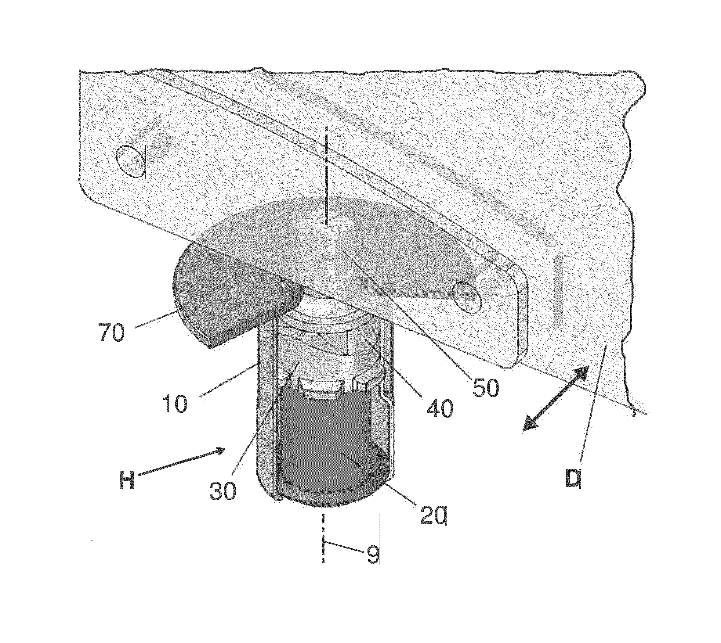
[0020]The present application provides an improved floor-mounted elastomeric spring hinge for doors which features a number of advantages over previous hydraulic springs. First of all, the spring hinge is relatively compact which lends itself to smaller recesses in the floor. Furthermore, the spring hinge is contained within a closed tubular housing which also helps prevent water ingress. Finally, the spring itself is a relatively durable and elastomeric which is corrosion resistant and predictable in its performance.

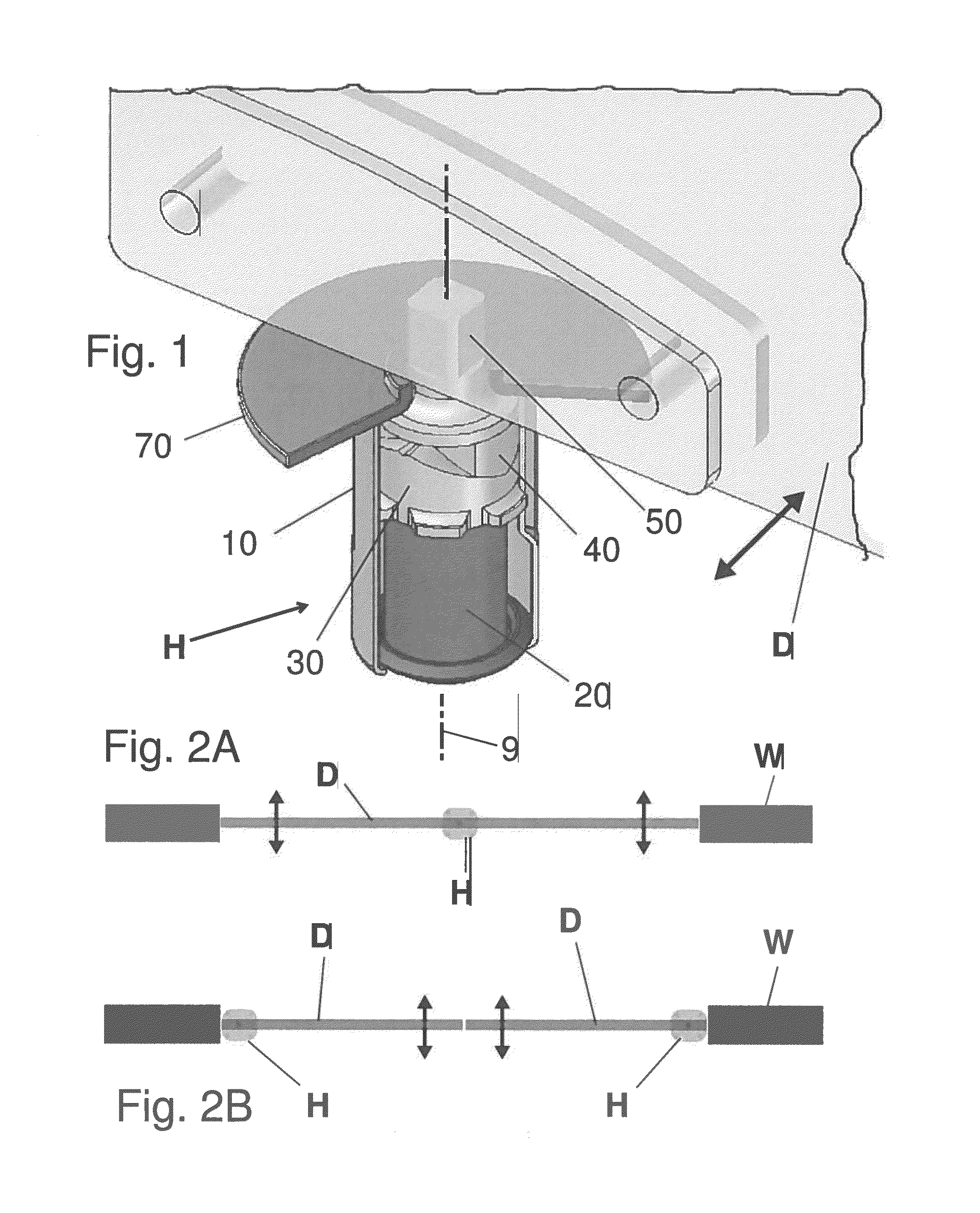
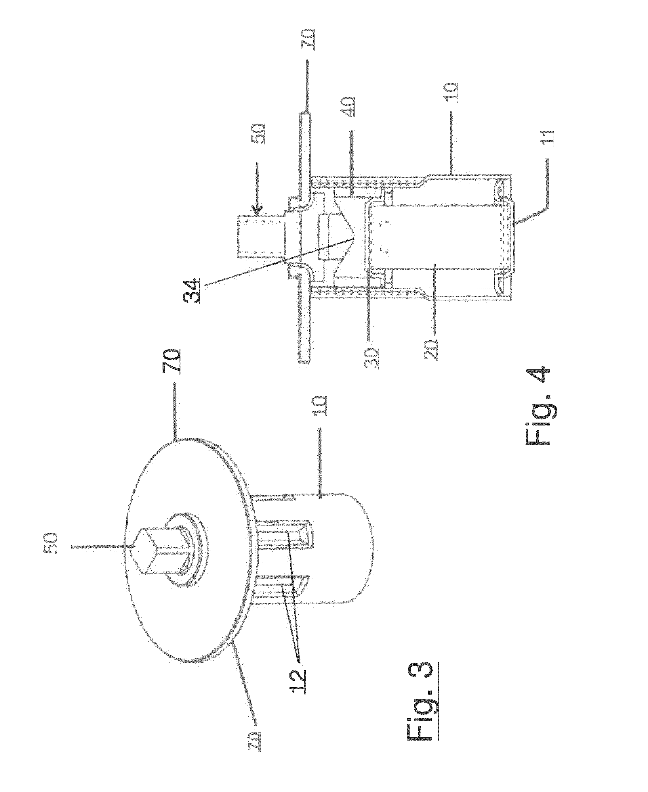
[0021]FIG. 1 is a partially cut-away perspective of an exemplary floor-mounted elastomeric spring hinge H mounted underneath one end of a door D. The door D can swing in either direction is indicated by the movement arrow, pivoting about an axis 9 corresponding with a central axis of the spring hinge H. In this regard, the outer components of the spring hinge H include a lower hollow tube 10 having a series of vertical splines 12 (see FIG. 3) formed in an upper portion ...


PUM

PropertyMeasurementUnit
depthaaaaaaaaaa
diameteraaaaaaaaaa
angleaaaaaaaaaa

Abstract

A constructive arrangement in elastomeric spring for closing doors which comprises a hollow tube having one end provided with a base and the inner area the provision of an elastomeric spring disposed juxtaposed to said base having a tracking member positioned on the elastomeric spring which receives the tracking member on the opposite face whose free end presents edge provided with female fitting which allows the positioning of a cam with male fitting pressed by a pin fixed to the tube through a bushing and having inner cap with fixing holes and protective cap.

Description

RELATED APPLICATION INFORMATION[0001]The present application is a continuation-in-part under 35 USC §§120, 363 and 365(c) of PCT Application No. PCT / BR2012 / 000506, filed Nov. 14, 2012, which designates the U.S. and in turn claims priority under 35 U.S.C. §119(a) to Brazilian Patent Application No. BR 20 2012 0074686 filed Apr. 2, 2012.BACKGROUND[0002]This application describes a constructive disposition on elastomeric spring for closing doors. More specifically, the application comprises an elastomeric spring within a hinge mechanism and a rotating pin for engaging a door particularly useful to be installed on the floor.[0003]The conventional hydraulic springs used with doors perform the automatic opening and closing of the door, with minimal effort, to both sides, having on both sides a function of fixed stop, where the door may be parked in a spot approximately 45 degrees.[0004]The floor hydraulic springs of the state of the art are set aligned with the door hardware, and a box is...

Claims


Application Information

Patent Timeline
Patent Type & Authority Patents(United States)
IPC IPC(8): E05D7/08
CPCE05Y2201/638E05F1/12E05F1/1223E05F1/14E05Y2800/678E05Y2201/474Y10T16/2774Y10T16/597Y10T16/552Y10T16/53826
Inventor FREITAS MARINHO, FRANCISCO ALANDA SILVA, RAIMUNDO RAUMIRO MAIAGOMES DE ARAUJO, MARIA DO SOCORRO
Owner BOSTON INNOVATION GATEWAY LLC
Why Eureka
Try Eureka