
Chain consisting of oval profile chain links, and method for producing a chain of this type

a technology of oval profile and chain link, which is applied in the direction of driving chains, engine components, mechanical equipment, etc., can solve the problems of not being able to improve the life of known chain links, the need to at least replace chain links worn out, and the cost of production of such chains, so as to achieve the effect of being easily used

Active Publication Date: 2014-08-26
PEWAG AUSTRIA
View PDF16 Cites 2 Cited by
  • Summary
  • Abstract
  • Description
  • Claims
  • Application Information

AI Technical Summary

Benefits of technology

The invention is a new type of chain design for profile chains that improves wear and load-bearing capacity while also minimizing stress concentration. The design includes special end webs with widened surfaces that form complementary cylindrical surfaces, which results in larger surfaces for articulation points between chain links. The wear behavior is significantly better than pure round chains with equal breaking force. The design also allows for easy storage and use of half links, reducing the need for differently formed partial links. The closed profile chain links can be easily created using friction welding, and plastic links can also be used.

Problems solved by technology

This results in the occurrence of wear at such articulation points of round steel chains under load, which can, in the end, result in the need to at least replace chain links worn out at the end webs of the articulation points, if not the need to replace the entire chain.
Since each individual chain link here has to be pre-bent into an open shape and then closed later by welding, the production of such chains is expensive.
The use, recommended there, of round stock on the end webs of these known chain links moreover also does not yield any improvements with respect to the life of these chain links due to joint wear.

Method used


Image

  • Chain consisting of oval profile chain links, and method for producing a chain of this type
  • Chain consisting of oval profile chain links, and method for producing a chain of this type
  • Chain consisting of oval profile chain links, and method for producing a chain of this type

Examples


Embodiment Construction

[0034]In the following description of the figures, parts with the same function in the various figures are also always provided with the same reference numbers.

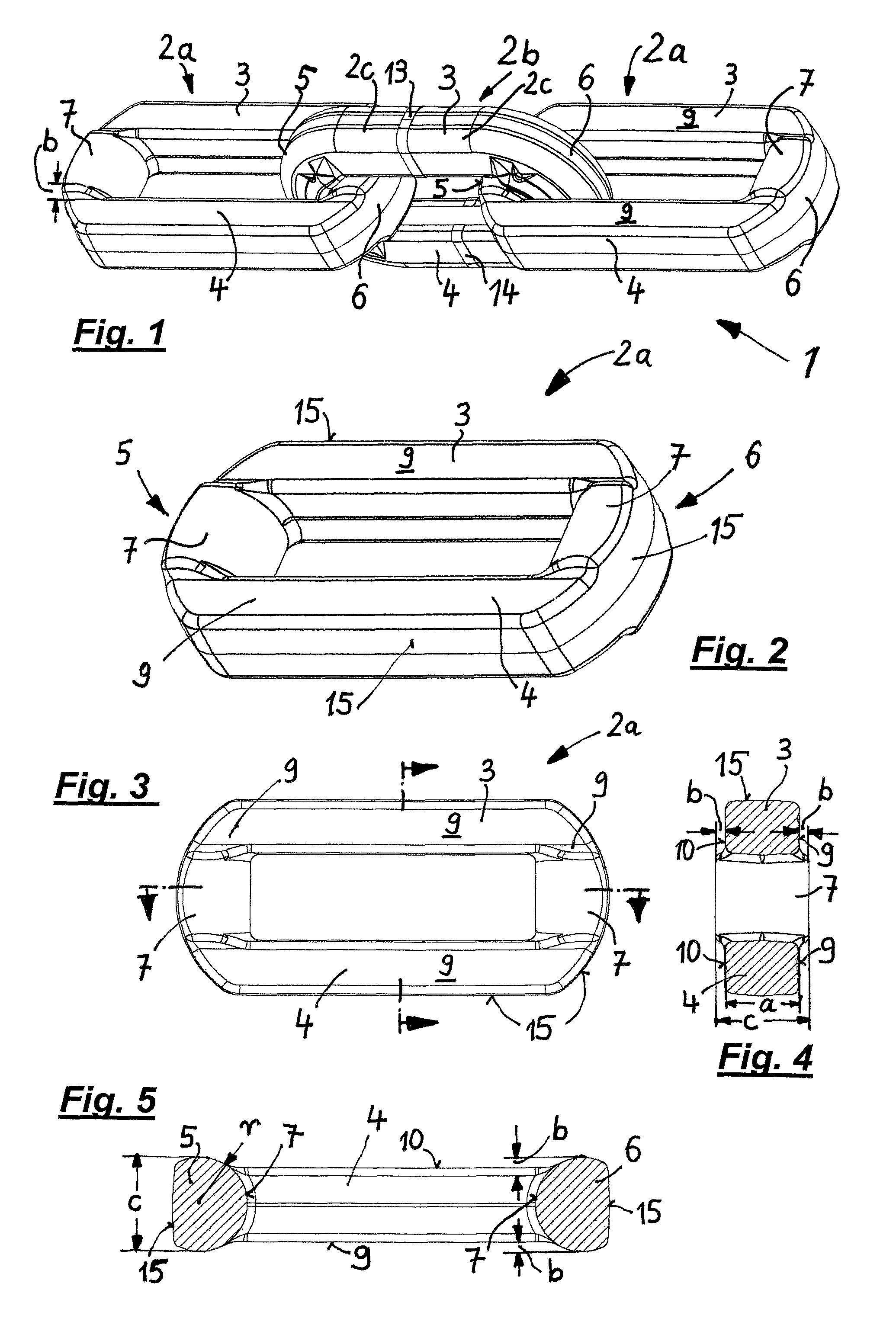
[0035]Firstly, in FIG. 1 a section from a chain 1 is shown in perspective representation, which comprises, in alternating sequence, two horizontal profile chain links 2a as well as two vertical profile chain links 2b, wherein in each case a vertical link 2b connects two horizontal links 2a, into which it is hooked in each case.

[0036]The horizontal links 2a and the vertical links 2b are elongate, oval profile chain links made of material that is not circular in cross-section, which will be discussed in detail below.

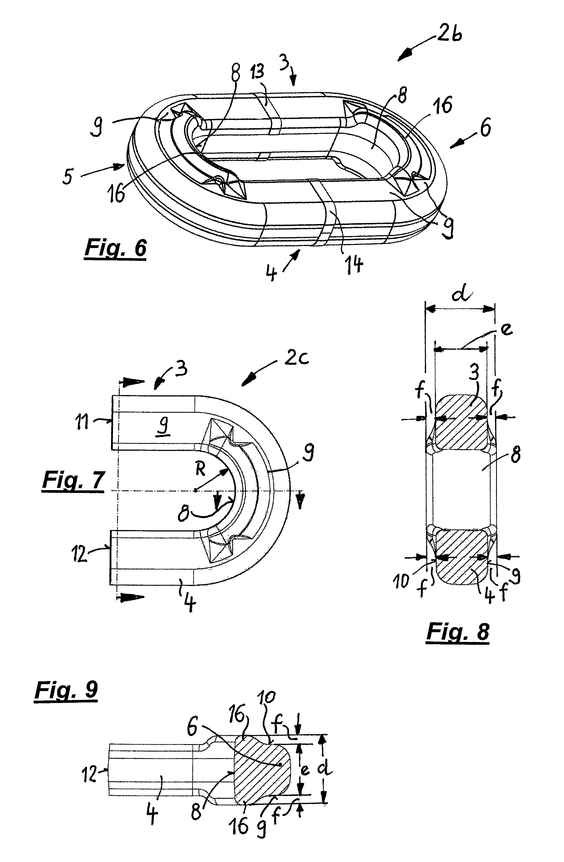
[0037]As FIG. 1 likewise shows, the horizontal links 2a are designed as one-piece, closed chain links, while the vertical links 2b consist in each case of two profile chain half links 2c which are welded together along weld points 13, 14 on their end faces 11, 12 facing one another (cf. FIG. 7) to form a closed vert...


PUM

PropertyMeasurementUnit
widthaaaaaaaaaa
lengthaaaaaaaaaa
widthaaaaaaaaaa

Abstract

A chain has alternating vertical and horizontal chain links and with each link having an oval profile. The vertical links having an end web supporting surface formed on its inside that engages with a complementary bearing surface on the end web of adjacent horizontal link. The supporting surfaces and the bearing surfaces of all end webs are widened beyond two lateral surfaces of the respective end web, and supporting surfaces and bearing surfaces associated with one another are formed in each case as complementary cylindrical surfaces extending between longitudinal limbs. A method for producing such, closed profile chain links are hooked into open profile chain links and then the latter are closed by welding. And wherein, all supporting surfaces and bearing surfaces associated with one another are formed in each case as cylindrical surfaces that complement one another.

Description

PRIORITY CLAIM[0001]The present application is a National Phase entry of PCT Application No. PCT / EP2011 / 001114, filed Mar. 7, 2011, the disclosure of which is hereby incorporated by reference herein in its entirety.FIELD OF THE INVENTION[0002]This invention relates to chains formed of oval profile chain links.BACKGROUND OF THE INVENTION[0003]Chains consisting of oval profile chain links are known in which the cross-sections of the sectional steels used, in particular on the end webs connecting the longitudinal limbs of the chain links at their ends, have a circular cross-section (US 2006 / 0053766 A1, DE 2007 061 512 A1).[0004]In other known chains (DE 10 2008 034 360 A1), although the cross-sections of the end webs do not have a circular cross-section, they are formed circularly rounded on their sides facing the inner opening of the chain link in question.[0005]In both cases, however, this has the result, when a finished chain is under tension, that the end webs in each case of two c...

Claims


Application Information

Patent Timeline
Patent Type & Authority Patents(United States)
IPC IPC(8): F16G13/12B21L5/02F16G15/12
CPCB21K1/76F16G13/00F16G13/12B21L3/00
Inventor PENGG, AEGYDFUCHS, FRANZ
Owner PEWAG AUSTRIA
Learn More