Braking device for a personal mobility vehicle

a technology for personal mobility vehicles and brake devices, which is applied in the direction of cycle brakes, cycle equipment, cycle brakes, etc., can solve the problems of insufficient friction resistance of conventional brakes, serious damage to motors or drive components, and undesirable foot brakes, etc., to achieve simple and convenient use, add additional cost and complexity, and low price

Active Publication Date: 2014-08-26
RAZOR USA
View PDF14 Cites 39 Cited by
  • Summary
  • Abstract
  • Description
  • Claims
  • Application Information

AI Technical Summary

Benefits of technology

[0009]With the use of electric scooters, a conventional foot brake may be undesirable. A conventional brake may not offer enough frictional resistance to stop a scooter wheel being driven by an electric motor within performance parameters comparable to, or expected by, users of conventional scooters. Additionally, if the scooter wheel used for applying the braking forces is the same wheel which is driven directly by the motor, using a conventional foot brake may cause serious damage to the motor or drive components. Using other braking mechanisms for electric scooters such as disc brakes or caliper brakes could add additional cost and complexity to the scooters, which are popular in due part to their relative low price and simplistic convenience.
[0010]Preferred embodiments of the electric scooter with foot brake assembly are configured to allow a user to apply a fender foot brake to at least one wheel of an electric motorized scooter which simultaneously cuts off power from the motor to the driven wheel. A user is able to use the foot fender brake to slow the speed of the scooter or bring the scooter to a complete stop without risking damage to the motor or drive mechanism if the user is simultaneously engaging the throttle control for the motor.
[0014]In a preferred embodiment in which an engagement portion of the fender foot brake assembly is operably connected to an electrical switch or relay, the electrical switch or relay and the engagement portion of the foot brake are positioned on the underside of the fender. In a preferred embodiment, the switch or relay and the engagement portion of the foot brake are positioned at the rotational connection point between the fender portion and the scooter body. In one embodiment, the switch or relay and the engagement portion of the foot brake is positioned away from the braking wheel. In yet another preferred embodiment, the switch or relay and the engagement portion of the foot brake is positioned such that these components are protected from external debris, moisture, or harmful contact with external elements and inaccessible by inadvertent and accidental contact by the foot of the user.

Problems solved by technology

With the use of electric scooters, a conventional foot brake may be undesirable.
A conventional brake may not offer enough frictional resistance to stop a scooter wheel being driven by an electric motor within performance parameters comparable to, or expected by, users of conventional scooters.
Additionally, if the scooter wheel used for applying the braking forces is the same wheel which is driven directly by the motor, using a conventional foot brake may cause serious damage to the motor or drive components.
Using other braking mechanisms for electric scooters such as disc brakes or caliper brakes could add additional cost and complexity to the scooters, which are popular in due part to their relative low price and simplistic convenience.

Method used


Image

  • Braking device for a personal mobility vehicle
  • Braking device for a personal mobility vehicle
  • Braking device for a personal mobility vehicle

Examples


Embodiment Construction

[0024]Reference will now be made in detail to various embodiments of the present technology. While numerous specific embodiments of the present technology will be described in conjunction with the alternative embodiments, it will be understood that they are not intended to limit the present technology to these embodiments. On the contrary, these described embodiments of the present technology are intended to cover alternatives, modifications and equivalents. Furthermore, in the following detailed description, numerous specific details are set forth in order to provide a thorough understanding of the present technology. However, it will be recognized by one of ordinary skill in the art that embodiments may be practiced without these specific details. In other instances, well known methods, procedures, compounds, compositions and mechanisms have not been described in detail as not to unnecessarily obscure aspects of embodiments of the present technology.

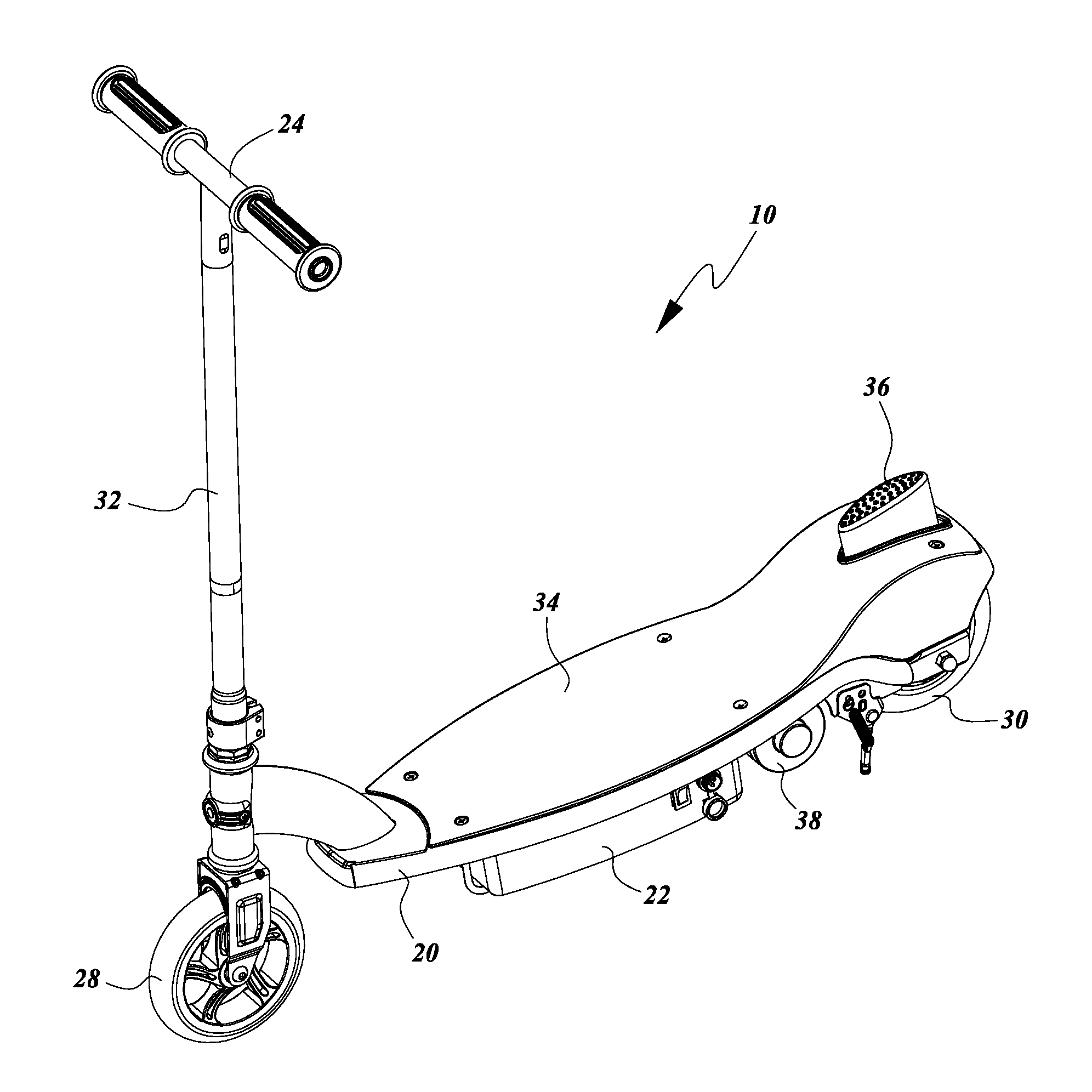
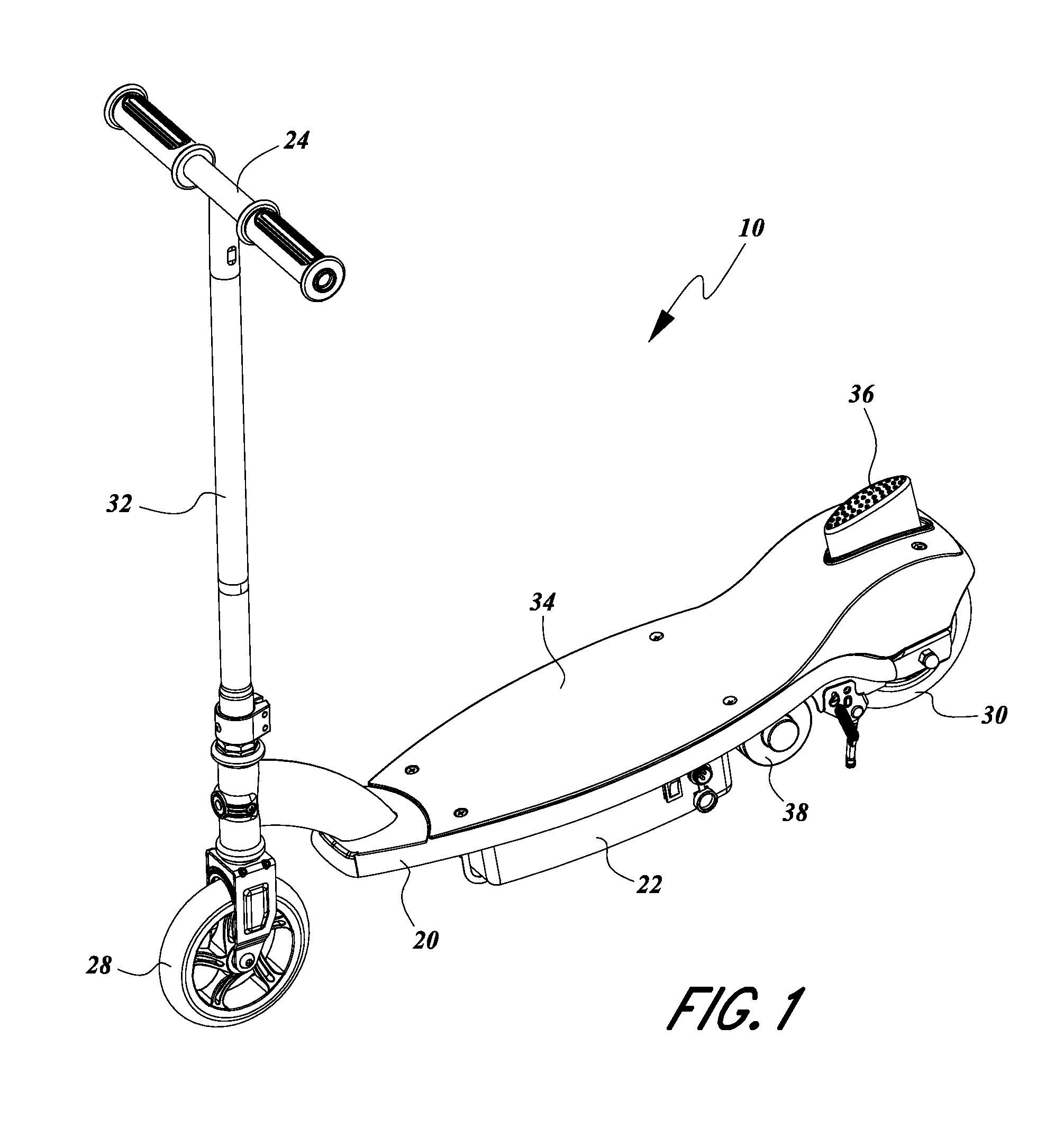
[0025]Referring now to FIG. 1, ...


PUM


Abstract

A personal mobility vehicle, such as a scooter, includes at least one battery and motor for powering at least one driven wheel. The vehicle also includes a braking assembly configured to isolate the motor from the at least one driven wheel such that power is terminated from the motor to the at least one wheel in response to a user engaging a braking assembly of the vehicle. The vehicle can include a switch or position sensor that interacts with the braking assembly to initiate the isolation of the motor from the at least one driven wheel and the switch or position sensor preferably is inaccessible to the foot of the user.

Description

PRIORITY INFORMATION[0001]The present application claims benefit under 35 U.S.C. §119(e) to U.S. Provisional Patent Application No. 61 / 589,177 filed Jan. 20, 2012, entitled “ELECTRIC SCOOTER WITH FOOT BRAKE,” the entire contents of which is hereby expressly incorporated by reference herein.BACKGROUND OF THE DISCLOSURE[0002]1. Field of the Invention[0003]Embodiments of the invention relate generally to personal mobility vehicles and, more specifically, to an electric scooter with a foot brake assembly.[0004]2. Description of the Related Art[0005]The use of personal mobility vehicles, such as scooters, has become a popular recreational activity as well as useful means of personal transportation. Scooters have become popular among many age groups and there are many different scooter variations and scooter designs. Conventional scooters have at least two wheels and a steering mechanism. Scooter designs have become more compact and convenient, and some scooters have folding mechanisms al...

Claims


Application Information

Patent Timeline
Patent Type & Authority Patents(United States)
IPC IPC(8): B62K11/00B62L1/00B62L1/04
CPCB62L1/00B62L1/04B62K23/08B62L3/04F16D2121/14B62K11/00B62K2204/00B62K3/002F16D49/00B62K2202/00B62K11/14
Inventor HADLEY, ROBERTCHEN, ROBERT
Owner RAZOR USA
Why Eureka
Try Eureka