Manufacturing method for upper support and upper support

a manufacturing method and support technology, applied in the direction of shock absorbers, mechanical devices, transportation and packaging, etc., can solve the problems of cracks that may develop in these portions, and achieve the effects of reducing the cost of such cracks, preventing the negative circumstance of variation, and reducing the deformation of the flanged portion

Active Publication Date: 2014-08-26
SUMITOMO RIKO CO LTD
View PDF21 Cites 7 Cited by
  • Summary
  • Abstract
  • Description
  • Claims
  • Application Information

AI Technical Summary

Benefits of technology

[0028]As described above, the invention of claim 1 is provided such that the cup piece also serving as the rebound stopper piece forms the inner piece and is integrally vulcanize adhered directly to the rubber elastic body. The cup piece is provided such that the shape of the tubular portion prior to integral vulcanized adhesion with the rubber elastic body is a shape having an upper portion continuous with the flanged portion as a large diameter portion, a lower portion on the base portion as a small diameter portion, and a portion between the large diameter portion and the small diameter portion as a stepped portion. Following integral vulcanized adhesion with the rubber elastic body, the small diameter portion is diameter widened by press-fitting a diameter widening jig into the small diameter portion to impart pre-compression to a portion of the rubber elastic body corresponding to the small diameter portion. Meanwhile, diameter widening is not performed on the large diameter portion, which retains its pre-established dimensions and shape.
[0029]In the manufacturing method of claim 1, the cylindrical inner piece conventionally necessitated as a separate body from the cup piece can be omitted, thus enabling the upper support to be made lightweight and to reduce the costs thereof. In addition, by widening the diameter of the tubular portion of the cup piece, pre-compression is imparted to the rubber elastic body, at which time deformation is not introduced to the upper portion of the tubular portion which continues to the flanged portion because diameter widening is performed only on the small diameter portion and is not performed on the upper portion of the tubular portion. Accordingly, upward roll-back deformation of the flanged portion of the cup piece due to diameter widening can be prevented. By diameter widening the small diameter portion, the small diameter portion elongates in a diameter widening direction. Thus, even when the small diameter portion is deformed, the large diameter portion, where deformation does not occur, exists between the small diameter portion and the flanged portion and so the tensile force accompanying deformation of the small diameter portion is blocked by the large diameter portion. The tensile force thus does not work on the upper surface of the flanged portion and accordingly, roll-back deformation of the flanged portion can be favorably prevented. Therefore, following diameter widening on the cup piece, a process to correct the shape of the flanged portion can be unnecessary, and therefore again, the negative circumstance of variation which arises in the reformative process can be eliminated. In addition, deformation due to deformation of the flanged portion can also be prevented for holes provided on the flanged portion for mounting on the vehicle body.
[0030]In such a case, the inner diameter of the upper end of the small diameter portion is made the same diameter as the inner diameter of the large diameter portion. Thus, the diameter of the small diameter portion can be widened until the stepped portion is removed (claim 2).
[0031]Furthermore, in such a case, the inner circumferential surface of the large diameter portion and the inner circumferential surface of the small diameter portion (specifically, the inner circumferential surface up to the bottom end of the portion at which pre-compression is imparted to the rubber elastic body) can be made to have a straight shape in an axial direction made continuous by the diameter widening of the small diameter portion (claim 3).
[0032]In the present invention, the outer piece is provided with an outer tubular portion having a shape surrounding the tubular portion of the cup piece at a position offset in a radially outward direction. The rubber elastic body has a tubular main body rubber portion sandwiched between the tubular portion and the outer tubular portion in a radial direction. Pre-compression is imparted to the main body rubber portion by diameter widening of the small diameter portion (claim 4). By doing this, pre-compression can be effectively imparted to the main body rubber portion, which intrinsically requires pre-compression, by diameter widening the small diameter portion.
[0033]In the present invention, the rubber elastic body is provided with a scooped-out portion at an axial direction position where the stepped portion is positioned. The scooped-out portion has an annular shape along a circumferential direction and is oriented in a radially inward direction from the outer circumferential surface toward the stepped portion. In the rubber elastic body, the main body rubber portion to which pre-compression is imparted by diameter widening of the small diameter portion and a stopper rubber portion on a rebound side on a bottom surface of the flanged portion can be separated in an axially vertical direction by the scooped-out portion across the entire radial direction (specifically, across the entire radial direction leaving a thin rubber portion on the outer circumferential surface of the stepped portion, the movement thereof being restricted by an adhesive) (claim 5).

Problems solved by technology

Besides this, when the tubular portion 206 of the cup piece is deformed to widen the diameter with the above-described method, there is a risk that a portion running from the bottom end of the tubular portion 206 to the base portion 208 may be warped or stressed by being greatly extended and, thus, a crack k may develop in these portions.

Method used


Image

  • Manufacturing method for upper support and upper support
  • Manufacturing method for upper support and upper support
  • Manufacturing method for upper support and upper support

Examples


Embodiment Construction

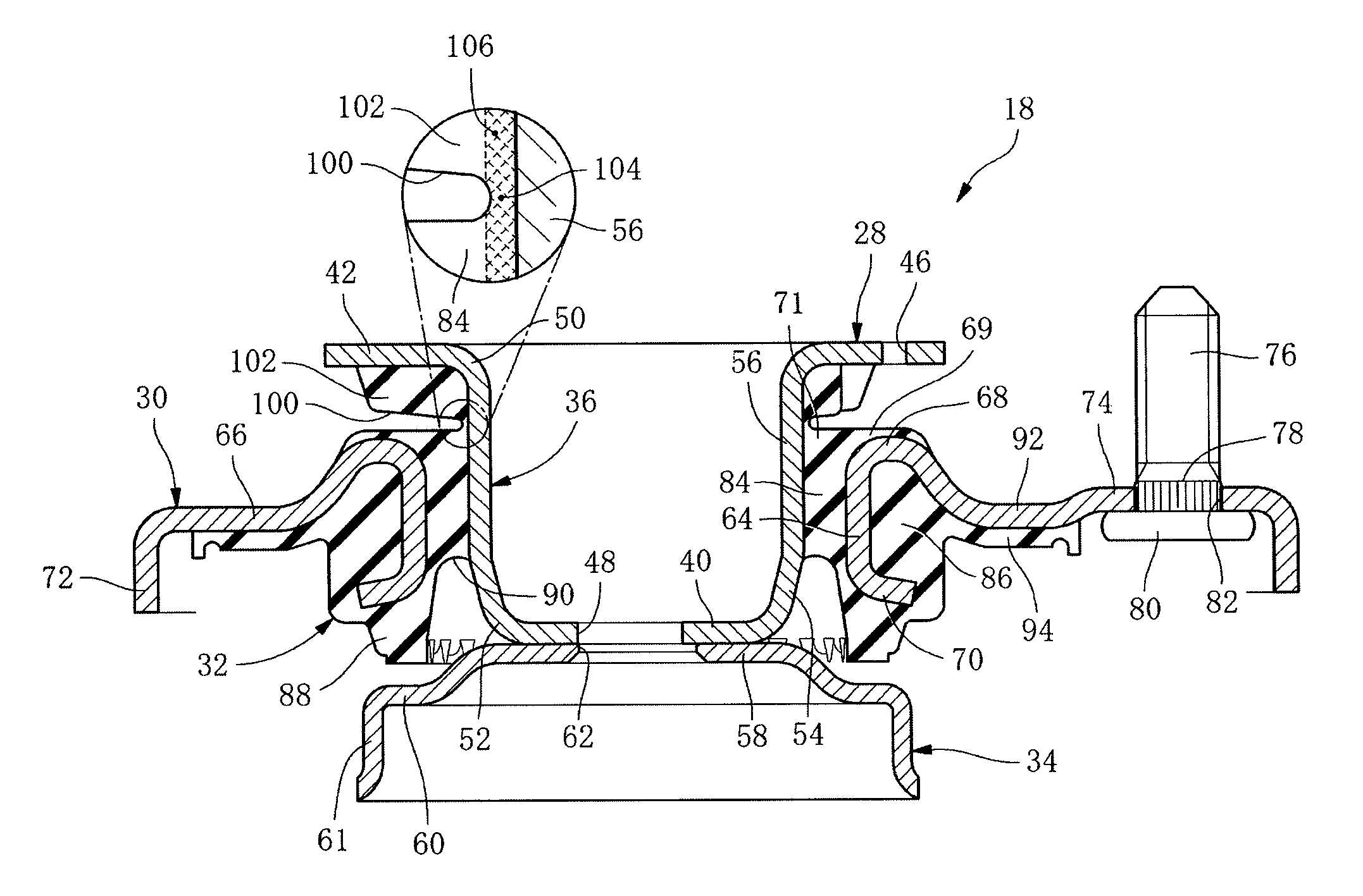
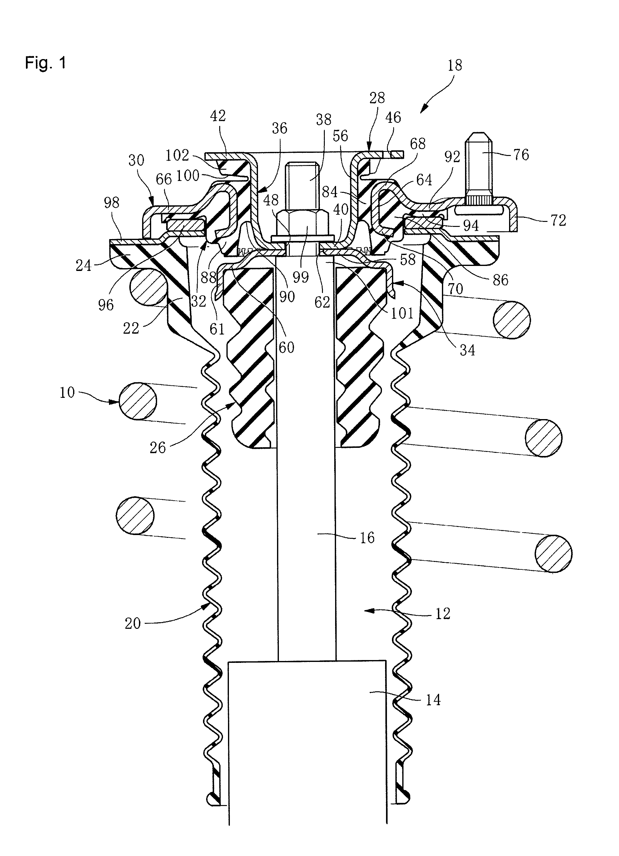
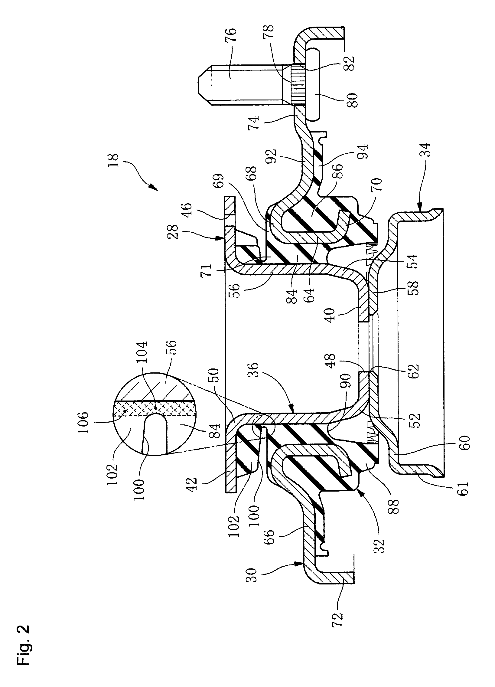
[0065]Next, an embodiment of the present invention will be described in detail with reference to the drawings. In FIG. 1, 10 is a metallic coil spring providing a suspension element of a vehicle; 12 is a shock absorber likewise providing a suspension element, and includes a cylinder 14 and a piston rod 16 jutting upward therefrom. 18 is an upper support of the present embodiment, which elastically connects the piston rod 16 and a vehicle body panel not shown in the figure, and which acts to prevent vibration therebetween.

[0066]20 is a dust cover into which the shock absorber 12 is inserted at a position on an inner side of the coil spring 10, and which has a cylindrical and overall zig-zag shape configured with a rubber elastic body. The dust cover 20 includes, at an upper portion, a large diameter portion 22 having thick walls, and a thick-walled flanged portion 24 having an annular shape in a circumferential direction jutting in an outward radial direction from the top end of the ...


PUM

PropertyMeasurementUnit
thicknessaaaaaaaaaa
heightaaaaaaaaaa
thicknessaaaaaaaaaa

Abstract

When manufacturing an upper support which includes a cup piece as an inner piece, an outer piece, and a rubber elastic body integrally vulcanize adhered thereto, the shape of a tubular portion of a cup piece before integral vulcanized adhesion with the rubber elastic body is a shape having a large diameter portion at a top portion continuous with a flanged portion, a small diameter portion at a bottom portion, and a stepped portion therebetween. Following integral vulcanized adhesion with the rubber elastic body, only the small diameter portion is diameter widened by press-fitting a diameter widening jig to impart pre-compression to the rubber elastic body. No roll-back deformation of a flanged portion occurs when integrally vulcanize adhering the cup piece to the rubber elastic body, and also when imparting pre-compression to the rubber elastic body by diameter widening a tubular portion of the cup piece.

Description

CLAIM OF PRIORITY[0001]This application is a continuation of PCT / JP2011 / 069806 filed Aug. 31, 2011, and claims the priority benefit of Japanese Applications No. 2010-217889, filed Sep. 28, 2010, and No. 2011-054520, filed Mar. 11, 2011, the contents of which is expressly incorporated by reference in its entirety.FIELD OF THE INVENTION[0002]The present invention relates to a manufacturing method for an upper support and an upper support elastically connecting a piston rod for a shock absorber in a suspension of a vehicle to a vehicle body, and acting to prevent vibration therebetween.BACKGROUND OF THE INVENTION[0003]Conventionally, a vehicle body and a piston rod for a shock absorber making up an element of a suspension in a vehicle have been elastically connected by an upper support. Vibration has been prevented or inhibited from being transferred from the shock absorber to the vehicle body side with the anti-vibration action of the upper support.[0004]Technology having a variety of...

Claims


Application Information

Patent Timeline
Patent Type & Authority Patents(United States)
IPC IPC(8): F16F9/54F16F1/38B60G15/06
CPCB60G15/068F16F1/3842F16F9/54B60G2204/128B60G2204/41
Inventor MATSUMURA, HIROYUKI
Owner SUMITOMO RIKO CO LTD
Why Eureka
Try Eureka