Eureka AIR delivers breakthrough ideas for toughest innovation challenges, trusted by R&D personnel around the world.

Resonance reduction device for ram air turbine

a ram air turbine and resonance reduction technology, which is applied in the direction of wind motors with perpendicular air flow, rail brake actuation, track-braking member co-operation, etc., can solve the problems of turbine imbalance, conventional ram air turbines can encounter self-induced vibration, etc., to reduce the space required, reduce resonance amplitude, and reduce vibration. undesired

Active Publication Date: 2014-08-26
HAMILTON SUNDSTRAND CORP
View PDF6 Cites 7 Cited by
  • Summary
  • Abstract
  • Description
  • Claims
  • Application Information

AI Technical Summary

Benefits of technology

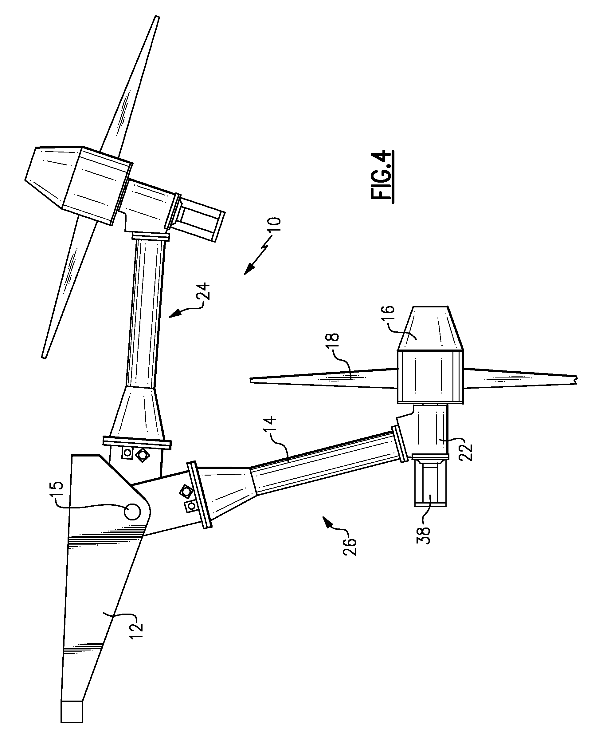
[0005]The preferential location of a mass modifies the structural frequency of the ram air turbine structure to reduce undesired vibrations that can occur during operation. Further, the example masses can be movable to reduce the space required for storage of the ram air turbine. The preferential location of a mass at specific locations on the ram air turbine can reduce resonance amplitude or otherwise modify structural resonance frequencies, thereby reducing the need to increase structural features of the overall ram air turbine assembly.

Problems solved by technology

Conventional ram air turbines can encounter self-induced vibrations caused by imbalance of the turbine.
The turbine imbalance is primarily caused by motion of the governor components and governor springs.

Method used


Image

  • Resonance reduction device for ram air turbine
  • Resonance reduction device for ram air turbine
  • Resonance reduction device for ram air turbine

Examples


Embodiment Construction

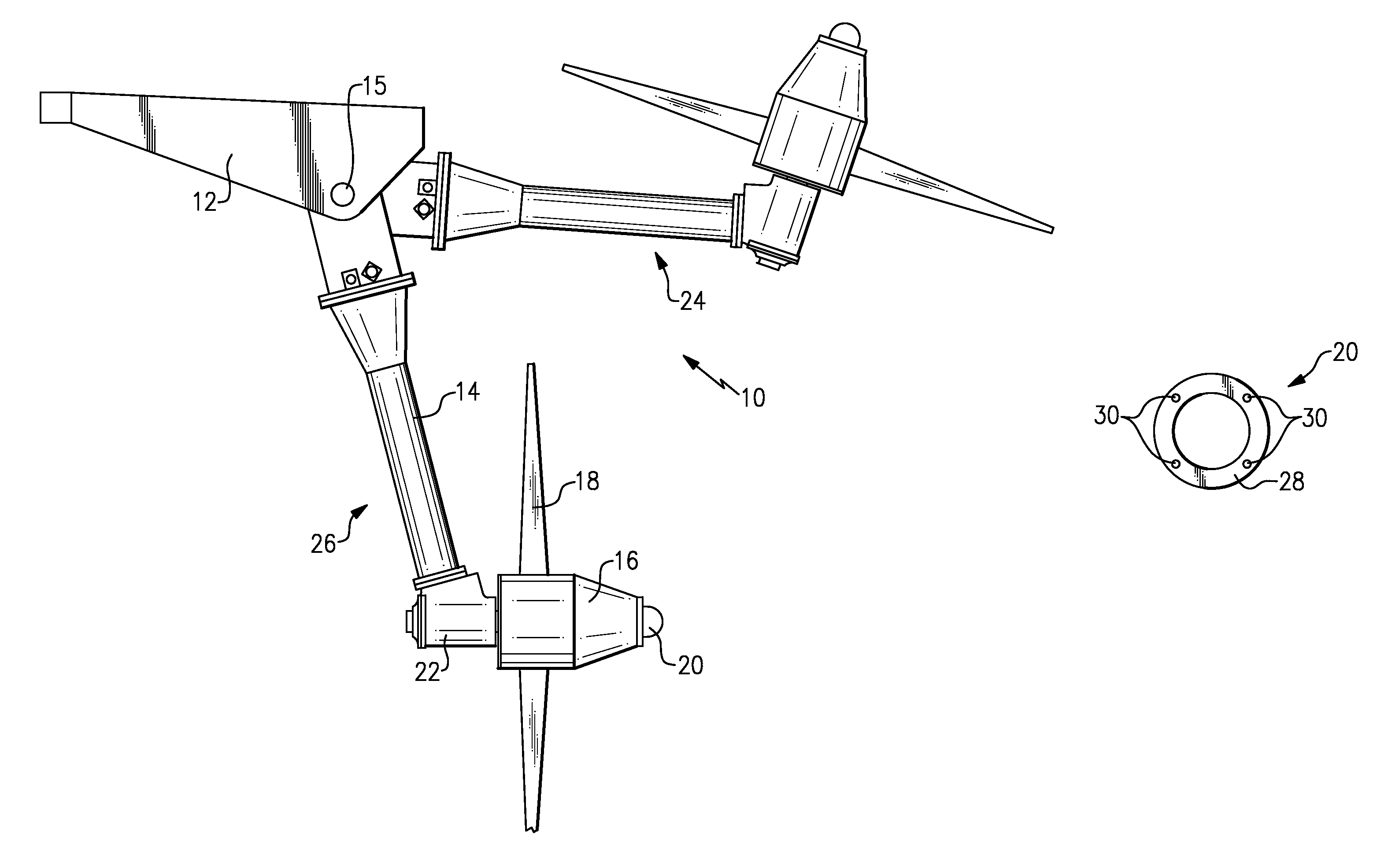
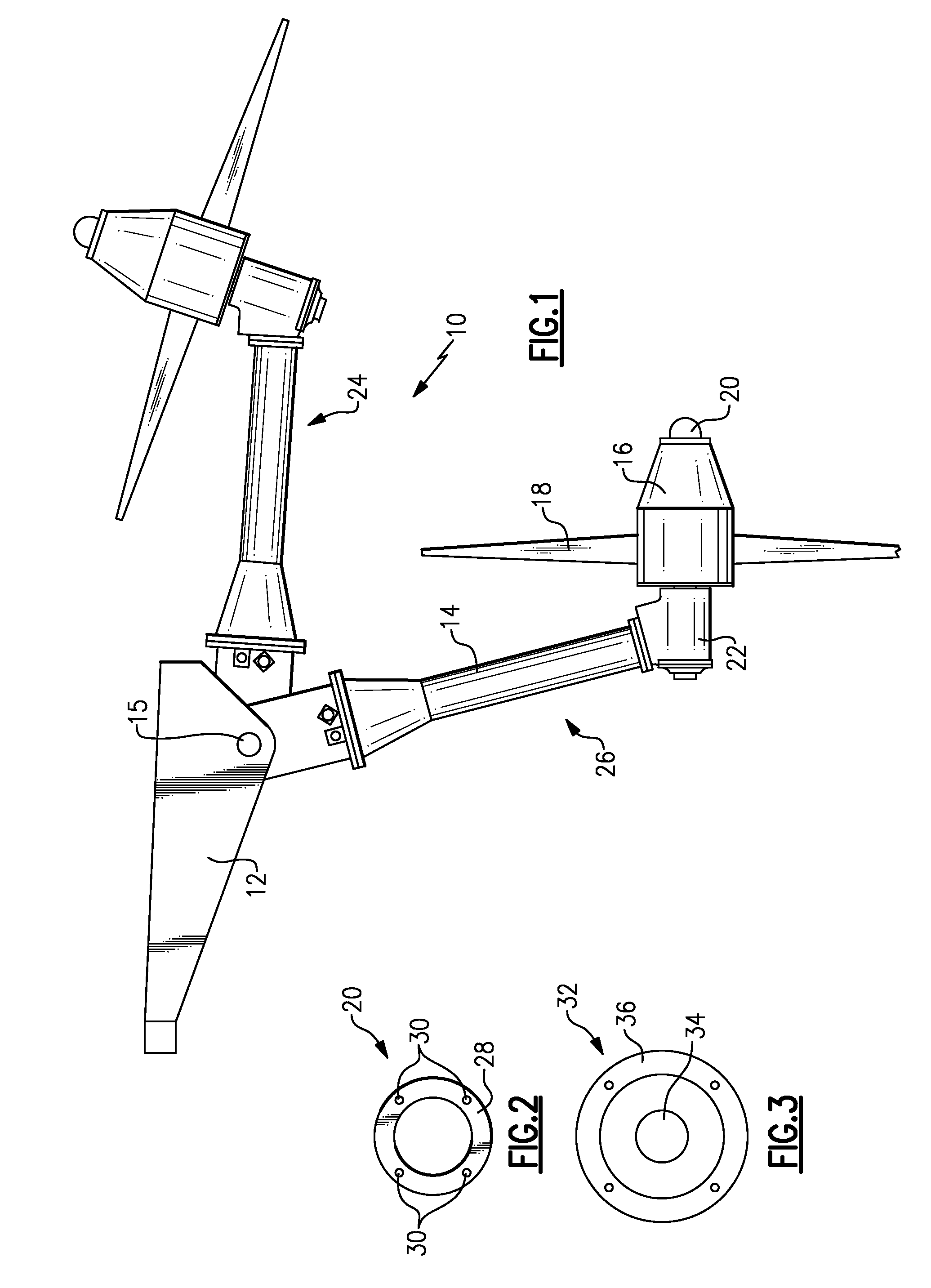
[0023]Referring to FIG. 1, a ram air turbine assembly 10 includes a deployable support structure 14 pivotally attached to a fixed structure 12. A rotating turbine hub 16 includes turbine blades 18 and is supported on a distal end of the support structure 14. The rotating hub 16 is supported on a housing 22 attached to the end of the support structure 14. The support structure 14 is movable about a pivot 15 between a stowed position 24 and a deployed position 26.

[0024]The example ram air turbine assembly 10 is shown and described by way of example, and other configurations and structures are within the contemplation of this invention. Further, the example ram air turbine assembly 10 operates to provide auxiliary power generation in the event that a primary power generating unit aboard an aircraft is not working as desired. In such a circumstance, the example ram air power generating assembly 10 is moved from the stowed position 24 to the deployed position 26 and the turbine blades 18...


PUM


Abstract

A ram air turbine assembly includes a preferentially located mass that modifies the resonance frequency of the assembly so that vibration is reduced to desired levels. The example mass can be fixed in a specific location on the ram air turbine or can be deployable once the ram air turbine is moved to an operating position.

Description

BACKGROUND OF THE INVENTION[0001]This disclosure generally relates to ram air turbine assemblies. More particularly, this disclosure relates to a method and device for reducing structural resonances of a ram air turbine assembly.[0002]A ram air turbine is utilized in aircraft as a backup power generator. Upon failure of the primary power generator, the ram air turbine is deployed. Deployment entails movement from a position within the aircraft to an extended position where the turbine blades are exposed to ram air outside of the aircraft. The turbine blades rotate a generator to provide electrical power, a pump to provide hydraulic power or both at the same time to aircraft systems in the absence of primary electrical and hydraulic power.[0003]The ram air turbine is a back-up device and therefore is rarely used. However, although rarely used, it is important that the ram air turbine operate efficiently and properly when deployed. Conventional ram air turbines can encounter self-indu...

Claims


Application Information

Patent Timeline
Patent Type & Authority Patents(United States)
IPC IPC(8): A47C7/74
CPCB64D41/007Y02T50/44Y02T50/40
Inventor RUSS, DAVID EVERETTBANNON, DAVID G.
Owner HAMILTON SUNDSTRAND CORP
Why Eureka
Eureka Blog
Learn More