Motor

a motor and motor technology, applied in the field of motors, can solve the problems of reducing the efficiency of the motor, increasing the cost of the motor, and the machine is therefore not good for frequent changes, so as to achieve the effect of widening the high rpm range, and reducing the cost of the motor

Active Publication Date: 2014-08-26
PANASONIC CORP
View PDF8 Cites 17 Cited by
  • Summary
  • Abstract
  • Description
  • Claims
  • Application Information

AI Technical Summary

Benefits of technology

[0015]The foregoing structure allows the motor to generate great torque at a low rpm because the magnetic poles opposing to each other of the inner and outer rotors have the same polarity, so that a greater number of magnetic fluxes inter-link with the windings. As a result, greater torque can be generated. The foregoing structure also allows the motor to widen a high rpm range because the magnetic poles opposing to each other of the inner and outer rotors have different polarities, so that a greater number of leakage magnetic fluxes is produced and thus a smaller number of magnetic fluxes inter-link with the windings. As a result, an induction voltage is lowered and the high rpm range can be thus widened.

Problems solved by technology

However, copper loss increases substantially at a greater amount of the field weakening current.
If the motor produces a greater copper loss than iron loss, this field wakening control method will substantially lower the efficiency of the motor.
This machine is thus not good for an application of frequent changes between two operation modes, namely, great torque at a low rpm and a high rpm.
Since this synchronous machine controls two steady angle positions in a rotating direction and counter-rotating direction, it is suitable for a generator motor rotating in a single direction; however, it cannot be used in an application of rotating in either directions.Patent Literature 1: Unexamined Japanese Patent Application Publication No. 2002-359953Patent Literature 2: Unexamined Japanese Patent Application Publication No. 2002-165426

Method used


Image

  • Motor
  • Motor
  • Motor

Examples


Embodiment Construction

[0021]An exemplary embodiment of the present invention is demonstrated hereinafter with reference to the accompanying drawings.

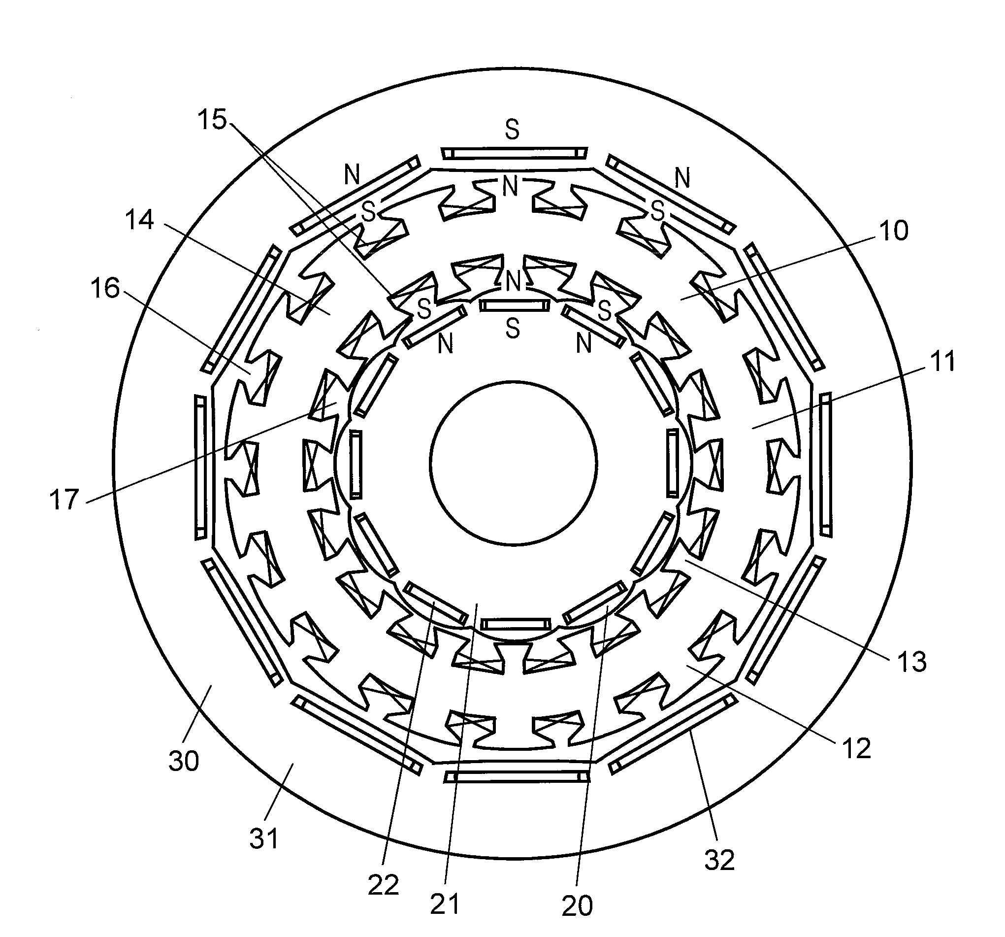
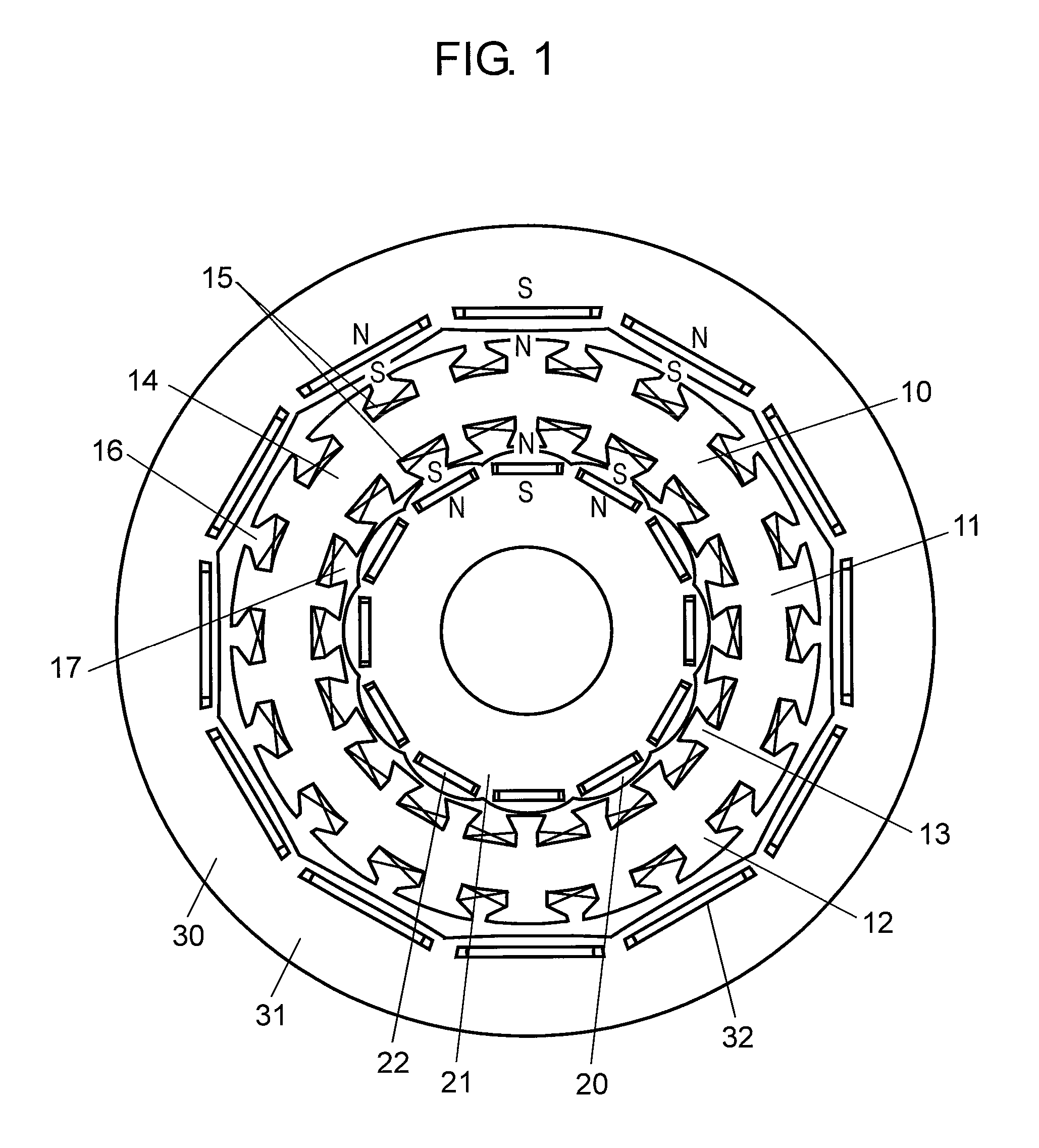
[0022]FIG. 1 shows a dual rotor motor in accordance with the embodiment of the present invention, and magnetic poles of an outer rotor have the same polarity as that of opposing magnetic poles of an inner rotor. FIG. 2 shows flows of magnetic fluxes of the dual rotor motor shown in FIG. 1. FIG. 3 shows a dual rotor motor in accordance with the embodiment of the present invention, and magnetic poles of an outer rotor have different polarity from that of opposing magnetic poles of an inner rotor. FIG. 4 shows flows of magnetic fluxes of the dual rotor motor shown in FIG. 3.

[0023]As shown in FIG. 1, the dual rotor motor in accordance with the embodiment includes stator 10, inner rotor 20, and outer rotor 30. Inner rotor 20 forms an interior-magnet type rotor in which permanent magnets 22 are approx. equidistantly placed along the outer circumference of inner-ro...


PUM


Abstract

A clutch mechanism moving together with an actuator allows coupling or decoupling an inner rotor to or from a power shaft, thereby controlling a rotation angle. This structure allows a polarity of a magnetic pole of the inner rotor to be the same as that of an opposing magnetic pole of an outer rotor when the motor is driven at a low rpm, so that magnetic fluxes inter-linking with windings can be increased, which results in greater torque. When the motor is driven at a high rpm, the structure allows the polarity of the magnetic pole of the inner rotor to be different from that of the opposing magnetic pole of the outer rotor, so that an amount of leakage flux is increased, and the magnetic fluxes inter-linking with the winding are decreased. As a result, an induction voltage is lowered and a high rpm range is widened.

Description

[0001]This application is a 371 application of PCT / JP2011 / 001309 having an international filing date of Mar. 7, 2011, which claims priority to JP 2010-050259 filed Mar. 8, 2010, the entire contents of which are incorporated herein by reference.TECHNICAL FIELD[0002]The present invention relates to a motor equipped with rotors both inside and outside a stator.BACKGROUND ART[0003]A dual-rotor type motor having rotors both inside and outside a stator can increase an amount of magnetic flux by capitalizing on the two rotors, thereby producing greater torque although the motor is compact size. This motor is hereinafter referred to as a dual rotor motor. The maximum rpm of this motor; however, is obliged to be lower under the condition of the power supply voltage being kept constant because an induction voltage proportional to magnetic flux inter-linking with the windings becomes higher. To obtain a greater range of a high rpm operation, an electric current for canceling the magnetic field...

Claims


Application Information

Patent Timeline
Patent Type & Authority Patents(United States)
IPC IPC(8): H02K16/00
CPCH02K21/029
Inventor LI, HUYOSHIKAWA, YUICHIMURAKAMI, HIROSHIMATSUO, HIDEAKITASHIRO, YUICHIRO
Owner PANASONIC CORP
Why Eureka
Try Eureka