Apparatus and method for controlling brushless electric motors and position encoders and indicating position thereof

Inactive Publication Date: 2006-04-25
PAPST MOTOREN GMBH & CO KG
View PDF24 Cites 12 Cited by
  • Summary
  • Abstract
  • Description
  • Claims
  • Application Information

AI Technical Summary

Benefits of technology

[0044]These problems are solved according to the invention by the measures given in claim 1 and the following claims. The invention makes it possible to increase the usable speed range compared with the

Problems solved by technology

It is disadvantageous that in place of an externally fitted sensor, there must be a sensor in the form of at least one additional measuring coil within the motor.
However, the circuit suffers from the disadvantage that a range of 360° el to be measured is split up into two undistinguishable ranges of in each case 180° el.
Moreover the precision of the position determination is limited to approximately ±60° el.
However, here again the position determination precision is not adequate and the typically attainable precision is limited to ±15° el.
However, in such cases the reliability is limited by that of the sensor

Method used


Image

  • Apparatus and method for controlling brushless electric motors and position encoders and indicating position thereof
  • Apparatus and method for controlling brushless electric motors and position encoders and indicating position thereof
  • Apparatus and method for controlling brushless electric motors and position encoders and indicating position thereof

Examples


Embodiment Construction

[0080]The inventive idea of solving the set problem comprises the following parts.[0081]a) A microprocessor is used. The novel current application necessary for measurement purposes is controlled by the microprocessor.[0082]b) The measurement and novel evaluation of the measured values is also controlled by the microprocessor with associated interface circuits.

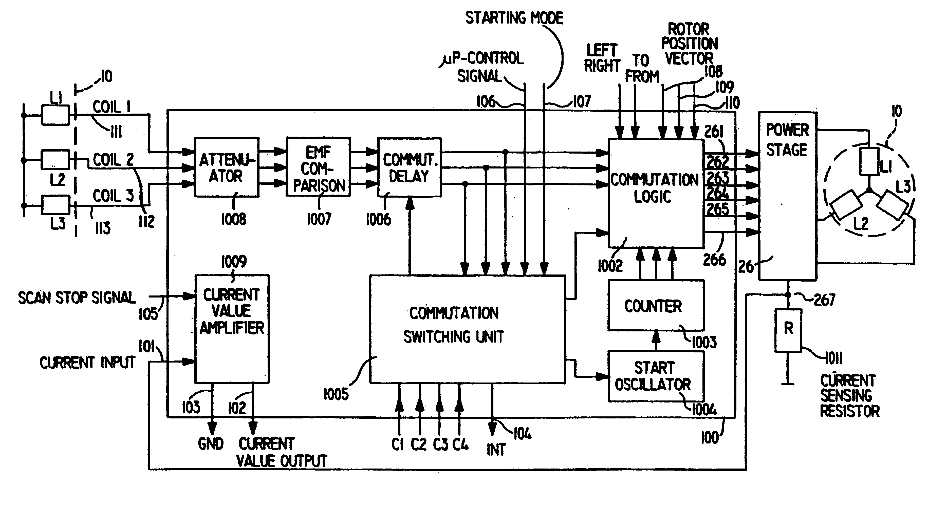
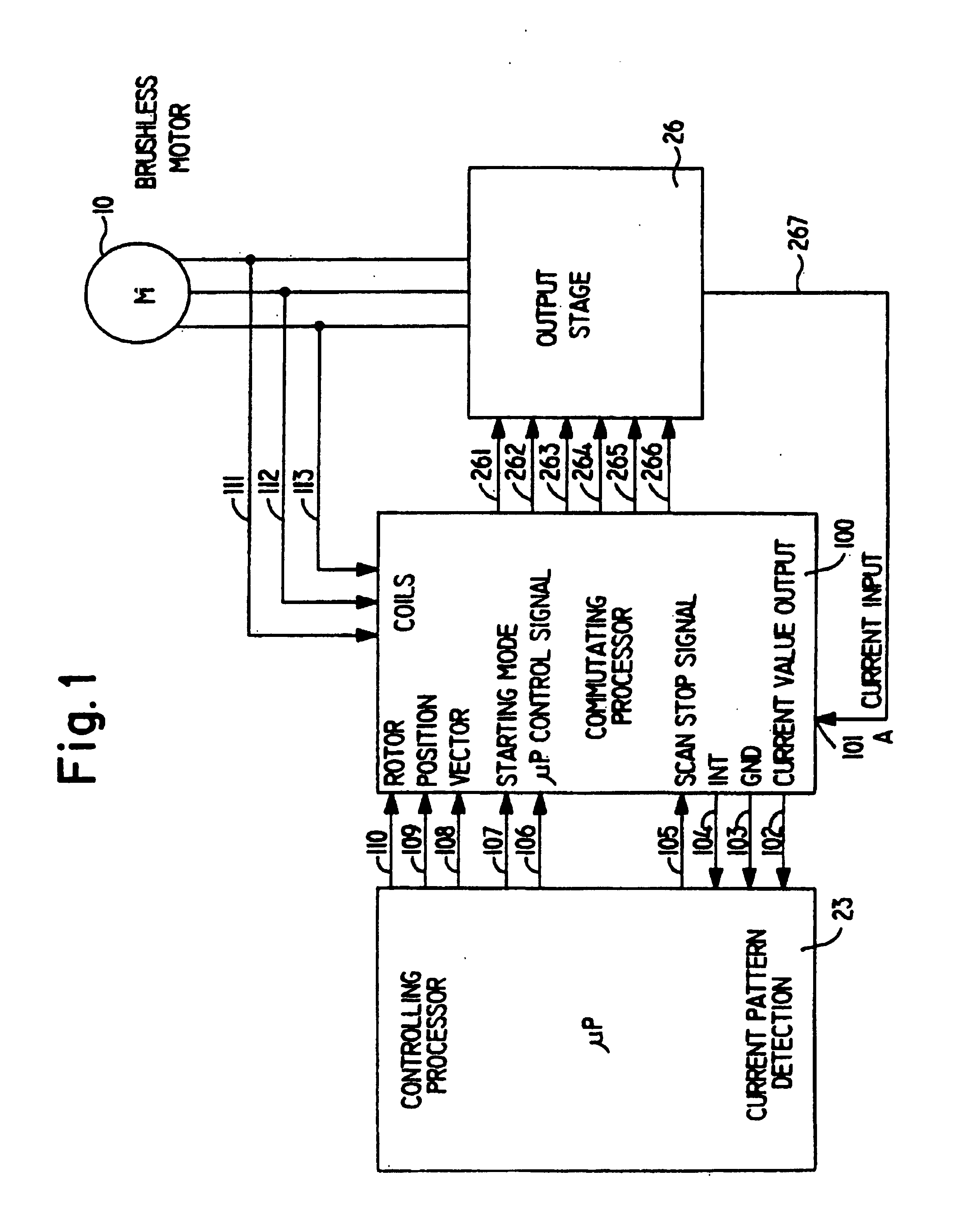
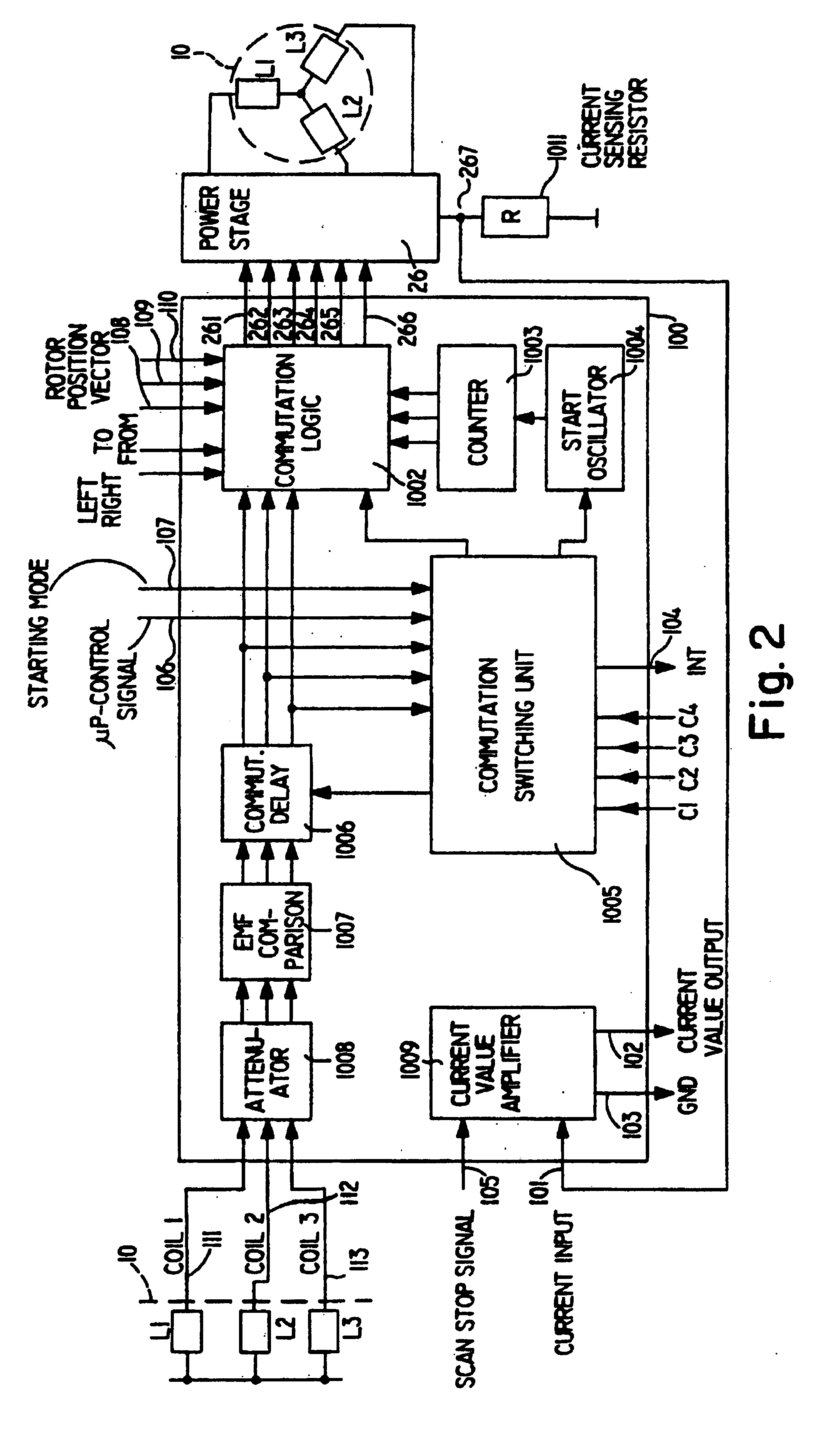
[0083]It must be borne in mind that cost-favourable microprocessors only have a low calculating speed and cannot normally match the problem to be solved. According to the invention for solving the specific problem the control and measurement processes to be performed can at least proportionally be processed by a special additional processor. The basic structure of such an inventive apparatus is shown in FIG. 1. Apart from the actual motor 10, it comprises an associated current application and output stage unit 26, a commutating processor 100 and the controlling or regulating microprocessor 23. Hereinafter the term processor is...


PUM


Abstract

A brushless direct current motor is energized by a power stage. Switches of the power stage are selectively switched by an electronic control device. In order to determine the correct commutation pattern, without using rotor position indicators such as Hall effect devices, the control device is arranged to sample the power fed to the motor. The samples, each responsive to a test signal or normal energization pulses received by the motor, in a ordered sequence define an analogue function whose parameters can be determined by mathematical analysis. The analysis applied to the samples derives the necessary commutation information and the energization signals in a rapid manner by employing a vector or complex number addition based on functions dependent on variable inductance in the operation of the motor.

Description

CROSS-REFERENCE TO RELATED APPLICATION[0001]The invention of this application is related to that of our copending patent application Ser. No. 07 / 805,154, filed Dec. 11, 1991.BACKGROUND OF THE INVENTION[0002]1. Field of the Invention[0003]The invention relates to a motor or a position indicator (position sensor) comprising an apparatus or method for controlling a brushless electric motor. The term motor is here understood to mean also e.g. a linear motor, whose position is to be detected. Both a rotary motor and a linear motor has as its movable part a rotor.[0004]2. Description of the Related Art[0005]Different types of position sensors are known and are e.g. used for determining the position of motor elements. In most cases there is an associated linear acting principle for a rotary acting principle. The most important classes of such position sensors or indicators are based on the following:[0006]Position sensors with direct contact with the movable element:[0007]a) Mechanical con...

Claims


Application Information

Patent Timeline
IPC IPC(8): H02P7/00H02P6/00H02P6/18H02P6/22H02P25/08
CPCH02P6/006H02P6/18H02P6/185H02P6/22H02P25/089
Inventor VON DER HEIDE, JOHANNMULLER, UWEHERMANN, MICHEAL
Owner PAPST MOTOREN GMBH & CO KG
Why Eureka
Try Eureka