Manufacture of electric motor component

a technology of electric motors and components, applied in the field of electric machines, can solve the problems of high cost of shipping assembled electric motors, prior art motors require special handling, and significant amount of air space, and achieve the effects of optimizing the power density of motors, maximizing available torque, and increasing the active length of stators

Active Publication Date: 2010-12-07
BURGESS NORTON MFG
View PDF16 Cites 11 Cited by
  • Summary
  • Abstract
  • Description
  • Claims
  • Application Information

AI Technical Summary

Benefits of technology

[0010]The stator face may be formed as a fully formed face of the stator pole having one or more, spaced tooth bodies extending therefrom. For example, a stator face having three tooth bodies attached, extending radially away from the stator face and spaced from each other may be formed. Three coils, each coil having an open core may be assembled onto the stator face having one coil disposed over each tooth body. A back iron and face are secured to each tooth body having the coil intermediate the back iron and the face to hold the coil on the tooth body. The back iron may be a three segment shape or may comprise three discrete back irons as discussed herein for securing the three coils on the spaced tooth bodies extending from the stator face. This integral stator face provides additional support to hold the coils in spaced relation and minimizes magnetic field disruptions caused by discrete edges between separate stator faces in a stacked component design. The back iron and the conical face on the tooth tip may both be formed with a single tooth body holding a single winding on the stator pole.
[0012]It's a feature of the present invention that such an improved conical stator assembly comprises a shape for optimizing the power density of the motor and maximizing available torque by increased moment arm at the big end of the conical design and increasing the active length of the stator. The conical design provides a larger moment arm at the big end for transferring the reactionary force of the interaction of the stator magnetic field and the rotor magnets to provide increased torque compared to a cylindrical design.
[0013]Torque is increased by the increased moment arm of the larger radial displacement of the rotor coils with respect to the axis of the rotor. This increased displacement takes advantage of the conical shape of the stator. Furthermore, the conical shape provides increased active length on the stator pole for increasing the flux conducted to the rotor. the modular shape allows the motor to securely fit into the space available based on the particular application.
[0014]Further, the rotor may be axially moved with respect to the stator. The rotor is moved in a direction of from the small end of the conical shape towards the large end of the conical shape to uniformly change the air gap between the rotor and stator to decrease back emf and weaken the rotor flux allowing an increased speed range for a permanent magnet motor design. This increase in air gap reduces the loses of the motor and the corresponding flux density exponentially.
[0015]Each stator component may be shipped as individual components for assembly in the field by a machine assembly team. Most motor failures are in the bearings or windings. The modular design allows the coil to be removed from the stator component, a new coil slipped onto the tooth body and the motor reassembled. Furthermore, in the event of a component failure, a modular stator component part of the electrical machine may be shipped for replacement without replacing the entire motor. In this way each pole of the conical shaped stator is maintainable at the motor site.

Problems solved by technology

Prior art motor designs use a significant amount of air space and can be large and heavy when assembled making shipping the assembled electric motor costly.
When installing or maintaining, prior art motors require special handling due to the size and weight.
Furthermore, prior art motors are not designed to be modular and capable of being broken down to separately shipped components.
Retooling is generally very expensive and requires down time from production while the tooling is modified or replaced.
Prior art symmetrically shaped cylindrical motors do not maximize the available mounting space available in installation locations.

Method used


Image

  • Manufacture of electric motor component
  • Manufacture of electric motor component
  • Manufacture of electric motor component

Examples


Embodiment Construction

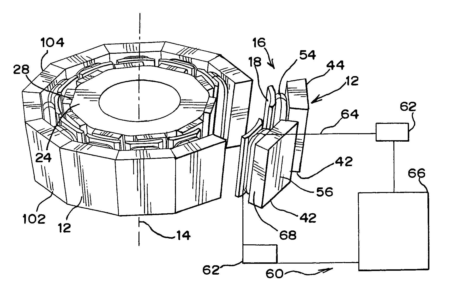
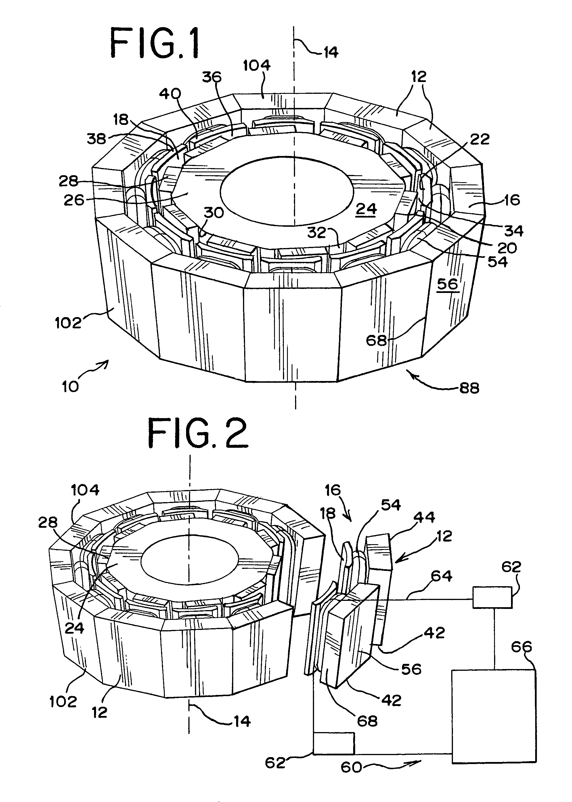
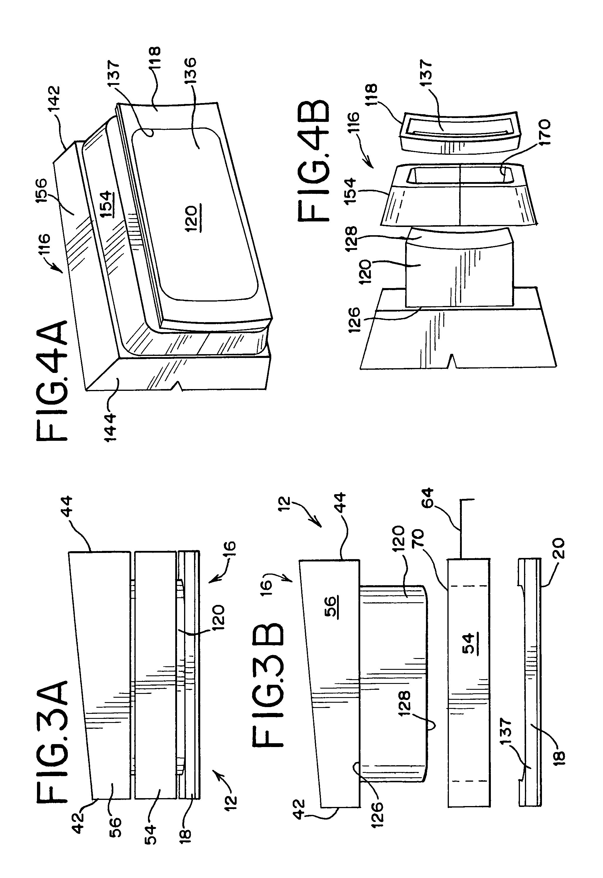
[0024]Referring to FIG. 1, the conical shaped stator 10 comprises a plurality of stator poles 12 assembled circumferentially about a stator axis 14. Each pole 12 comprises a modular molded tooth 16. The tooth 16 comprises a stator face 18 and a tooth body 120 (FIG. 3b). The stator face 18 has a generally rectangular shape tilted at an axial angle to define the conical shaped interior surface 20 defining a rotor space 22. A rotor 24 is rotatably mounted in the rotor space. The rotor 24 is axially aligned along the axis 14 of the stator and held in place by bearings or the like (not shown) to rotate in the rotor space. The rotor comprises a core 26 having a plurality of magnets 28 disposed along the outer perimeter 30. The magnets 28 are isolated from each other by dividers 32. Each magnet 28 defines a pole on the rotor 24. the outer perimeter 30 is precisely machined to maintain a predetermined air gap 34 between the rotor 24 and the stator 10.

[0025]The stator 10 surrounds the rotor ...


PUM

PropertyMeasurementUnit
soft magneticaaaaaaaaaa
concave shapeaaaaaaaaaa
magnetic fieldaaaaaaaaaa

Abstract

The modular conical stator pole provides an improved conical stator assembly on electrical machines. The improved conical stator pole assembly comprises a plurality of stator poles, each pole comprising an assembly having a coil secured on a soft magnetic composites (SMC) stator pole tooth by inserting a winding support through the open core of the coil and attaching a back iron and a stator face to either end of the winding support. Each stator pole having a parallelogram shaped cross section for forming a conical shaped rotor space when the stator poles are assembled having the back irons bearing against each other to space the coils apart and form a conical shaped outside profile of the stator pole assembly. The conical stator having a small end and a big end. The tooth comprising a winding support integrally molded with either the back iron or the face.

Description

BACKGROUND OF THE INVENTION[0001]The present invention relates to electrical machines and more particularly a design and method of manufacture for a conical stator assembly.[0002]Electric motors and generators have a stationary element, termed a stator and movable or rotating elements termed the rotor. The interaction between the stator and the rotor is caused by the interaction on a magnetic field generated by either the stator or the rotor. Such magnetic field is usually generated or induced by electric currents in a winding placed on either the stator or the rotor or both. The forces imparted on the rotor are a function of the interaction of the stator and the rotor magnetic fields and the moment arm of the rotor calculated by the radial displacement of the magnetic field of the rotor with respect to the axis of the rotor. Such stator winding usually comprises a plurality of coils wound around a winding support. The winding support is usually comprised of a soft magnetic material...

Claims


Application Information

Patent Timeline
Patent Type & Authority Patents(United States)
IPC IPC(8): H02K15/12H02K1/18H02K1/28
CPCH02K1/148H02K15/022Y10T29/49009
Inventor FARNIA, DAVID
Owner BURGESS NORTON MFG
Why Eureka
Try Eureka