
Interpreting angular orientation data

a technology of angular orientation and data, applied in the field of interpreting angular orientation data, can solve the problems of affecting the range of motion of the patient's joint, the inability of the goniometer to continuously measure, and the cumbersomeness of setting up the mechanical goniometer, so as to improve the patient's range of motion and facilitate us

Inactive Publication Date: 2014-08-26
KONINKLIJKE PHILIPS ELECTRONICS NV
View PDF18 Cites 24 Cited by
  • Summary
  • Abstract
  • Description
  • Claims
  • Application Information

AI Technical Summary

Benefits of technology

This patent text describes a need for a better way to measure the range of motion in physiotherapy. This helps motivate patients and show them that they are improving. It also wants to eliminate the need for calibration and alignment, which makes the system easier to use.

Problems solved by technology

However, setting up a mechanical goniometer for measuring the range of motion of a joint of a patient can be cumbersome.
Furthermore, a goniometer may not be suitable to measure continuously during each repetition of a physiotherapy exercise.
This may involve calibration errors.
Moreover, a movement about a vertical rotation axis cannot be recognized properly.

Method used


Image

  • Interpreting angular orientation data
  • Interpreting angular orientation data
  • Interpreting angular orientation data

Examples


Embodiment Construction

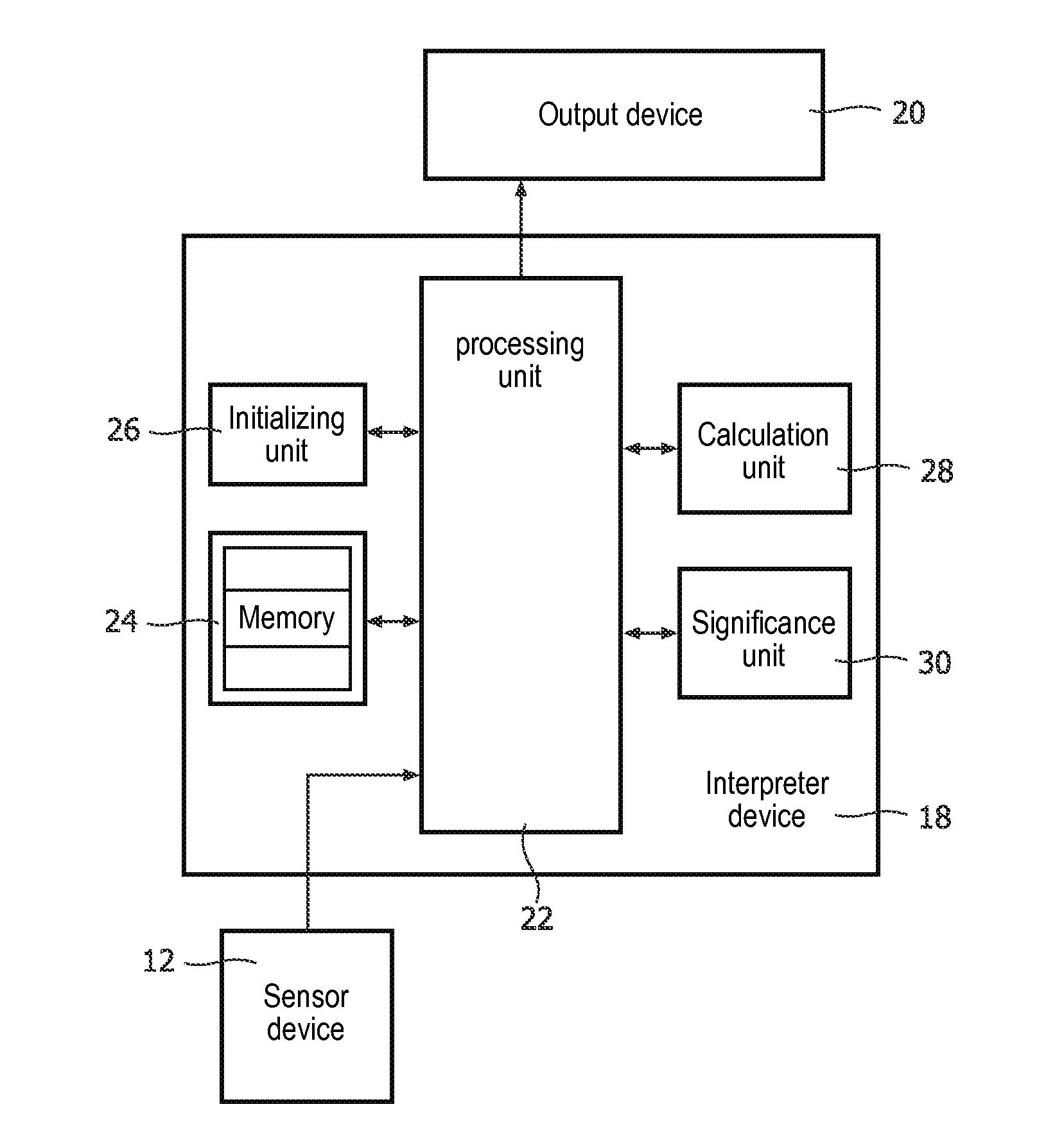
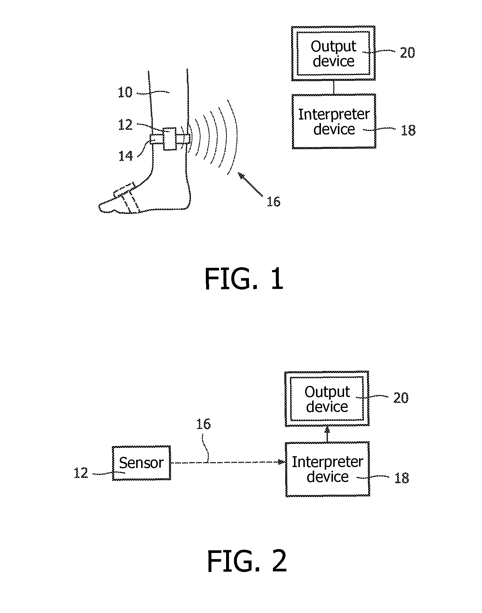
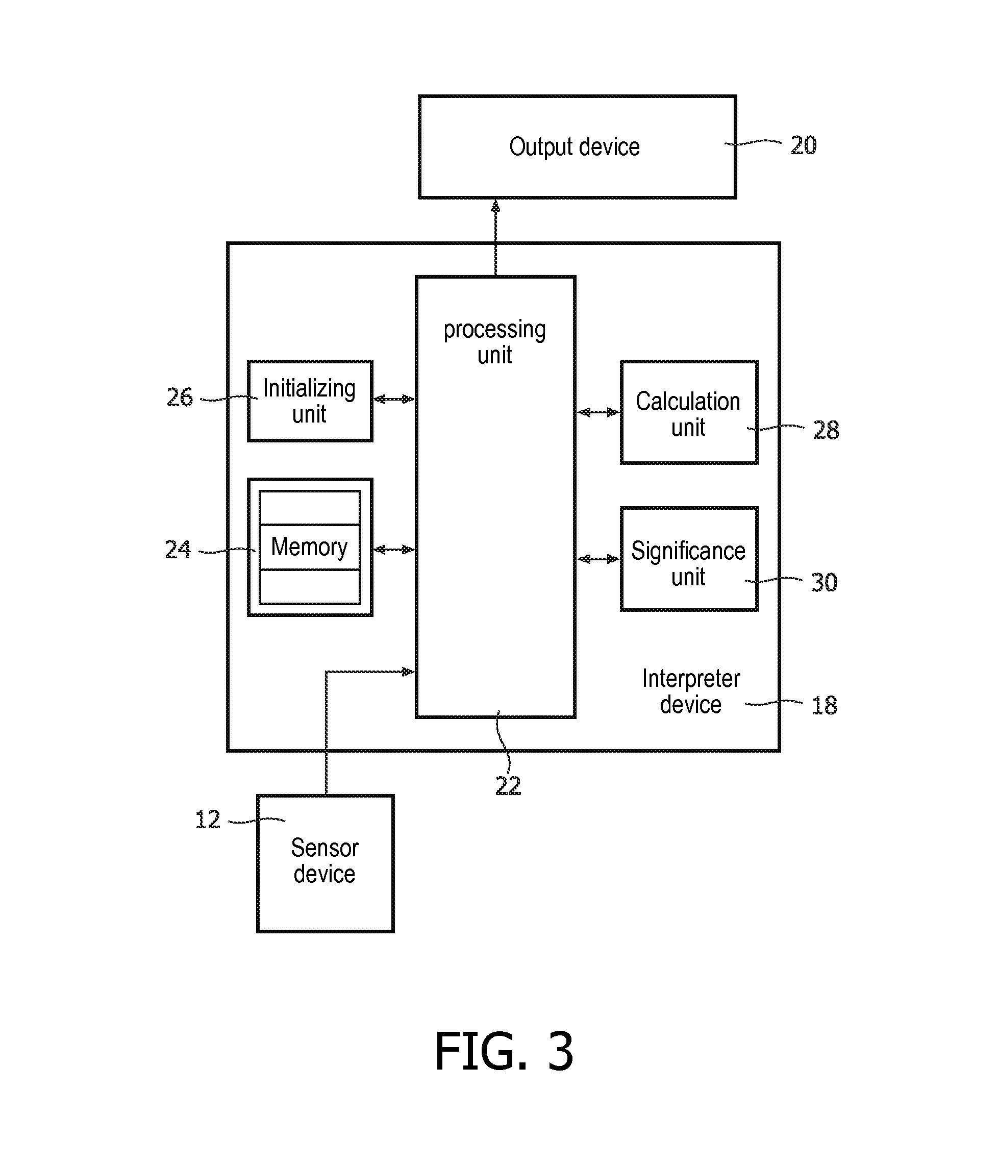
[0043]FIG. 1 exemplarily shows a system for interpreting angular orientation data of a body part 10. For example, the body part is a lower leg of a patient. A sensor device 12 is attached to the body part 10, for example using a textile elastic strap 14. Thus, the patient can easily attach the sensor device 12 to his own lower leg or other body part, the motion of which is to be monitored.

[0044]The sensor device 12 comprises, for example, various sensors for measuring angular orientation of the sensor device in three dimensions. For example, the sensor device 12 may include a 3D-accelerometer for measuring gravity and a 3D-magnetometer for measuring the earth magnetic field to provide a static drift free orientation. Furthermore, the sensor device 12 may comprise three gyroscopes to track fast changes in orientation. Such a sensor device is, for example, the Philips PI-node or the Xsens MTx orientation tracker.

[0045]Because the sensor includes a 3D-accelerometer, the sensor device c...


PUM


Abstract

The invention relates to method and a system of interpreting angular orientation data. It is determined, whether the angular deviation of a current angular orientation (C) of a sensor device (12) from a last extreme angular orientation (L) currently decreases after having increased before up to a provisional new extreme angular orientation (P), thereby determining that the provisional new extreme angular orientation (P) is a new extreme angular orientation. Information relating to a new extreme angular orientation, such as an angular range of motion, may be output to a user.

Description

FIELD OF THE INVENTION[0001]The invention relates to a field of interpreting angular orientation data, and more specifically to interpreting angular orientation data of a body part and, more specifically, to determining an angular range of motion of a body part.BACKGROUND OF THE INVENTION[0002]From WO 2007 / 008930 A2, a method of monitoring a range of motion of a body part is known, wherein a housing including a sensor is positioned against said body part, and wherein, in a first measuring step, a first orientation of an apparent gravity force acting on said housing is obtained while said body part has a first orientation relative to adjoin to which said body part is coupled and, in a second measuring step, a second direction of the apparent gravity force acting on said housing is obtained, while said body part has a second orientation relative to the joint. In a determining step, a magnitude of rotation of said body part from the first orientation to the second orientation is determ...

Claims


Application Information

Patent Timeline
Patent Type & Authority Patents(United States)
IPC IPC(8): G06F15/00G01B21/00A61B5/103A61B5/107
CPCA61B5/1038A61B5/1071A61B2562/0219
Inventor VAN ACHT, VICTOR MARTINUS GERARDUSBONGERS, EDWIN GERARDUS JOHANNUS MARIALAMBERT, NICOLAAS
Owner KONINKLIJKE PHILIPS ELECTRONICS NV
Learn More