Flight unit control system, flight control device including such a system, and use of such a system

Active Publication Date: 2014-09-02
SKF AEROSPACE FRANCE SAS
View PDF13 Cites 6 Cited by
  • Summary
  • Abstract
  • Description
  • Claims
  • Application Information

AI Technical Summary

Benefits of technology

[0007]The object of the present invention is to provide an improved flight unit control system designed for detecting reliably and precisely the en

Problems solved by technology

However, generally these systems lack reliability and are complicated to integrate into the actuator.
Consequently, it is necessary to modify the a

Method used


Image

  • Flight unit control system, flight control device including such a system, and use of such a system
  • Flight unit control system, flight control device including such a system, and use of such a system
  • Flight unit control system, flight control device including such a system, and use of such a system

Examples


Embodiment Construction

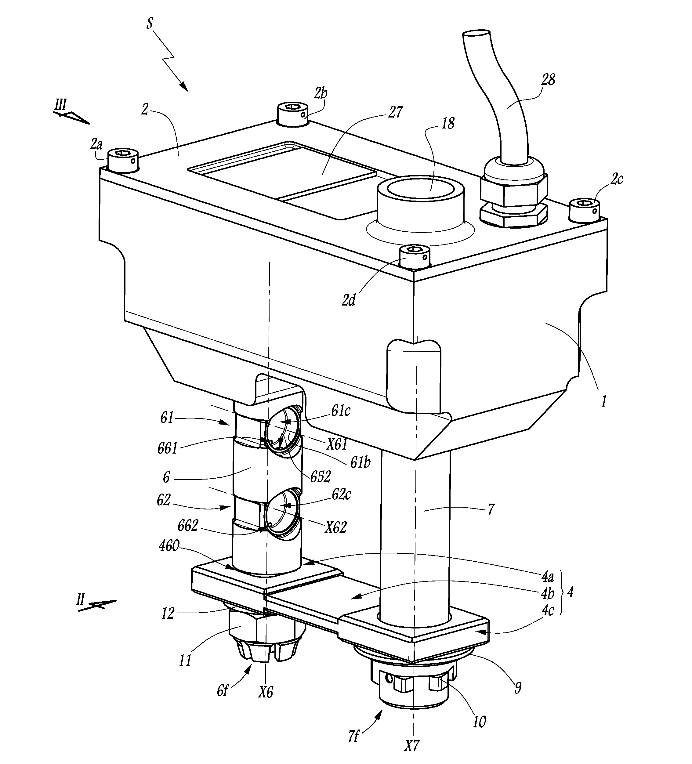
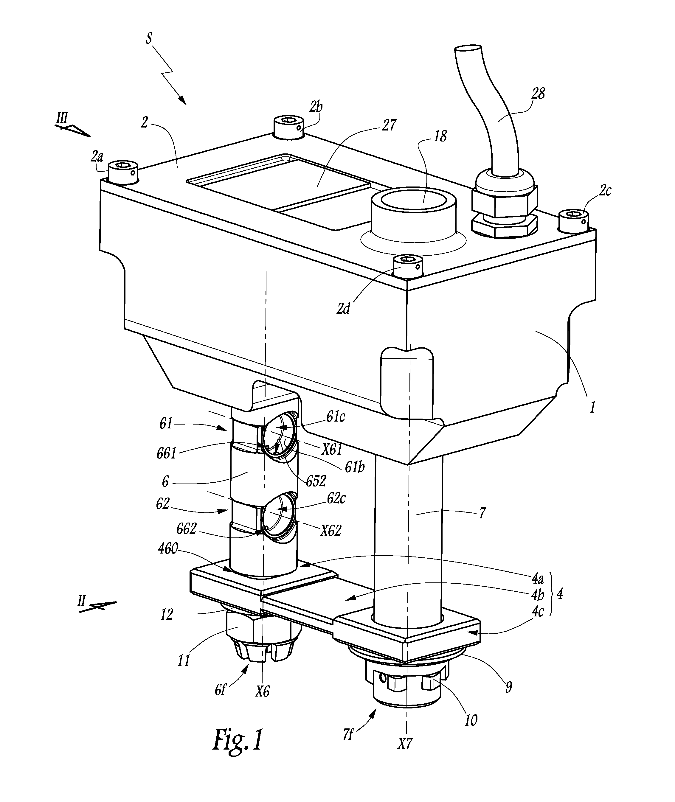
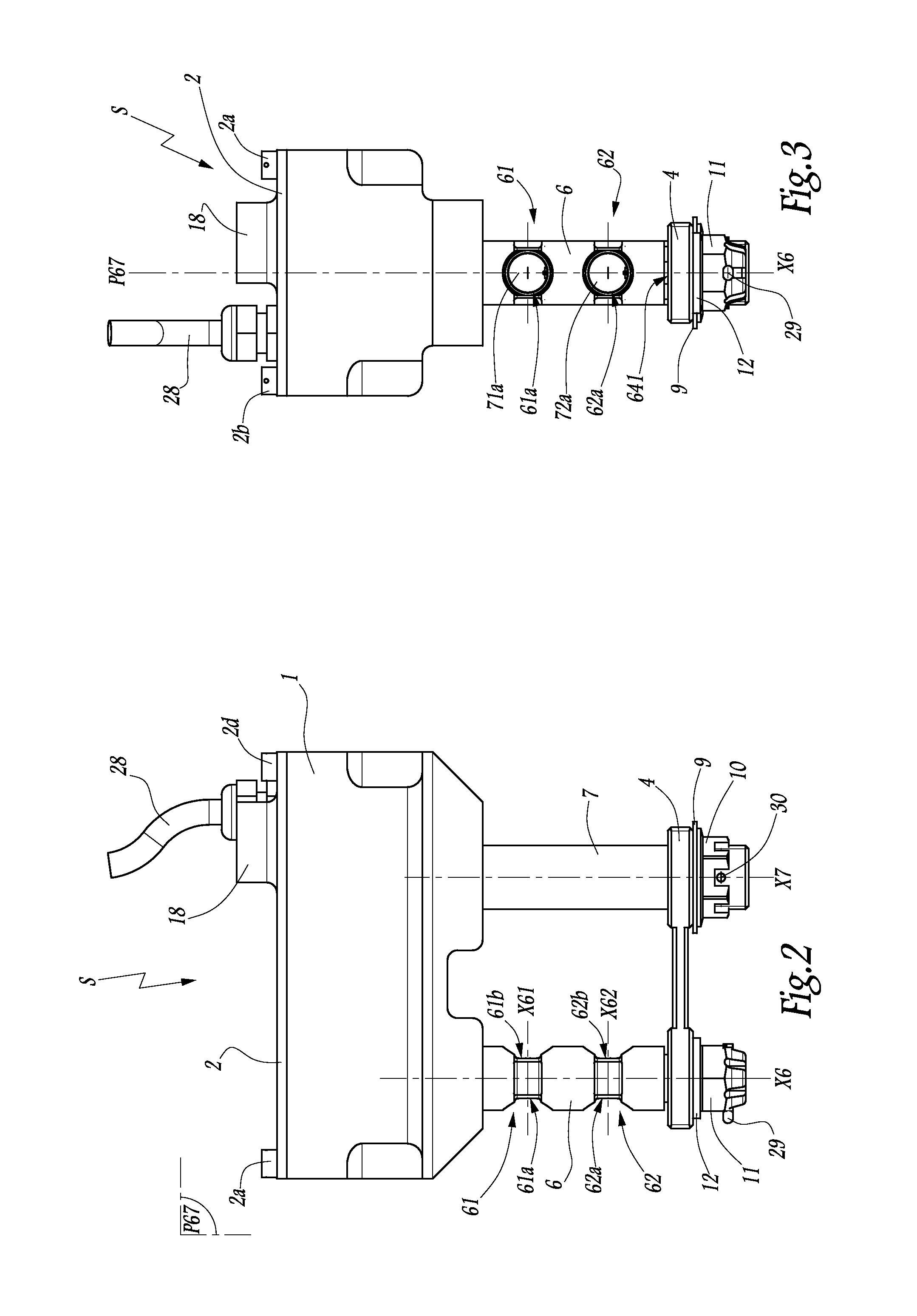
[0048]FIGS. 1 to 18 show a flight unit control system S.

[0049]In practice, the system S is in the form of a load sensing kit or LSK, ready to be installed on the secondary load path SLP of an aircraft flight unit, in particular on a THSA. Such an LSK is shown by itself, in one mounting configuration, in FIGS. 1 to 3.

[0050]Moreover, the system S can be seen in an operating configuration with the various elements of the SLP, in FIGS. 4 to 9, these figures making it possible to distinguish certain details that are otherwise difficult to appreciate, and also in FIGS. 17 and 18. Furthermore, FIGS. 10 to 16 show only an instrumented fastening bolt 6 with which the system S is equipped, as will be explained in detail later.

[0051]The system S comprises a casing 1 provided with a cover 2. As shown in FIGS. 7 to 9, a seal 25 is placed in the cover 2 and is sealed around the internal perimeter of the casing 1. An electronic card 3 is placed in the casing 1, held in place by screws 38 and linke...


PUM

PropertyMeasurementUnit
Forceaaaaaaaaaa
Structureaaaaaaaaaa
Tensile stressaaaaaaaaaa

Abstract

A flight unit control system having at least one instrumented fastening bolt connecting an aircraft carrier structure and a load path, the instrumented bolt having at least one measurement area for detecting that the load path is under load and including a fastener for locking the instrumented bolt in a position relative to the aircraft carrier structure and load path and wherein the measurement area has two cavities and at least one strain gauge and wherein the fastener includes a plate which is positioned at a threaded end of the instrumented bolt which bears against one of the aircraft carrier structure and the load path and which extends perpendicularly to an axis of the bolt and a nut which is placed at the threaded end of the instrumented bolt to immobilize the instrumented bolt relative to the aircraft structure or the load path.

Description

BACKGROUND OF THE INVENTIONField of the Invention[0001]The present invention relates to a flight unit control system. The invention also relates to a flight control device that includes such a system. Finally, the invention relates to the use of such a system for replacing a pre-existing system.[0002]In particular, the invention is intended to be implemented on the secondary load path of an aircraft flight control actuator, for example an actuator of the THSA (Trimmable Horizontal Stabilizer Actuator) type, which is intended for controlling the pitch motivator, i.e. the angle of inclination of the tail of the aircraft relative to the nose of the aircraft.BRIEF DESCRIPTION OF THE RELATED ART[0003]As is known, such a THSA comprises a primary load path or PLP and a secondary load path or SLP. In normal operation, the load passes through the primary path, whereas in the event of failure of the primary path the load passes via the secondary path. In this case, the secondary path provides...

Claims


Application Information

Patent Timeline
IPC IPC(8): F16B31/02B64C9/02B64C13/28
CPCB64C13/28B64C9/02Y10T29/4973B64C13/341
Inventor BOUILLOT, FRANCKMILORD, CEDRIC
Owner SKF AEROSPACE FRANCE SAS
Why Eureka
Try Eureka