Selectable dual mode trigger for semiautomatic firearms

a dual-mode, semi-automatic technology, applied in the direction of firing/trigger mechanism, weapons, shoulder-fired small arms, etc., can solve the problems of prohibitively expensive and difficult to acquire automatic weapons, and inability to meet the needs of the industry, so as to enhance the reliability of the trigger system, quick and easy transition, and double the effect of fire ra

Active Publication Date: 2014-09-02
FOSTECH INC
View PDF5 Cites 39 Cited by
  • Summary
  • Abstract
  • Description
  • Claims
  • Application Information

AI Technical Summary

Problems solved by technology

Automatic weapons are also known to be prohibitively expensive and harder to acquire than semi-automatic firearms.
Some of these solutions attempt to make it easier to “bump fire”, or use the firearms recoil to allow user to manipulate trigger faster, but these solutions fail to meet the needs of the industry because of complicated non-intuitive operation or undesirable add on devices.
Other solutions attempt to use mechanical means such as crank or slide devices to manipulate trigger quickly, but these solutions are similarly unable to meet the needs of the industry because non-intuitive operation with difficulty maintaining accurate fire.
Still other solutions, for example U.S. Pat. No. 6,966,138 to Deckard, seek to convert a standard trigger to fire a shot on both pull and release, but these solutions also fail to meet industry needs because the device needs to be installed and removed to switch between modes of operation, and are not compatible with trigger systems with a forward hammer engagement surface such as AR-15 and AR-10 pattern rifles, one of the most popular rifles in the United States.
Deckard's device also has no means of eliminating the possibility of “hammer follow” in the double-fire mode.
The hammer will follow the bolt assembly forward, resulting in the aforementioned automatic fire or requiring manually reciprocating the bolt assembly to resume firing.
Thus this device would not gain approval by the Bureau of Alcohol, Tobacco, Firearms and Explosives Firearms Technology Branch for civilian sales.

Method used


Image

  • Selectable dual mode trigger for semiautomatic firearms
  • Selectable dual mode trigger for semiautomatic firearms
  • Selectable dual mode trigger for semiautomatic firearms

Examples


Embodiment Construction

FIGS. 1-16

[0062]Before explaining the disclosed embodiment of the present invention in detail it is to be understood that the invention is not limited in its application to the details of the particular arrangement shown since the invention is capable of other embodiments. Also, the terminology used herein is for the purpose of description and not of limitation.

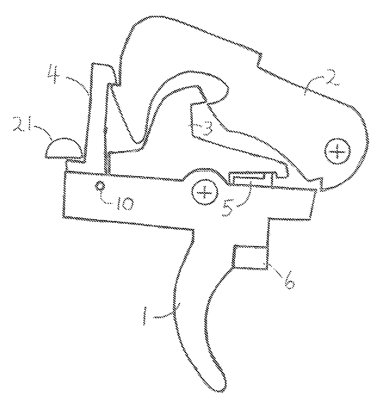
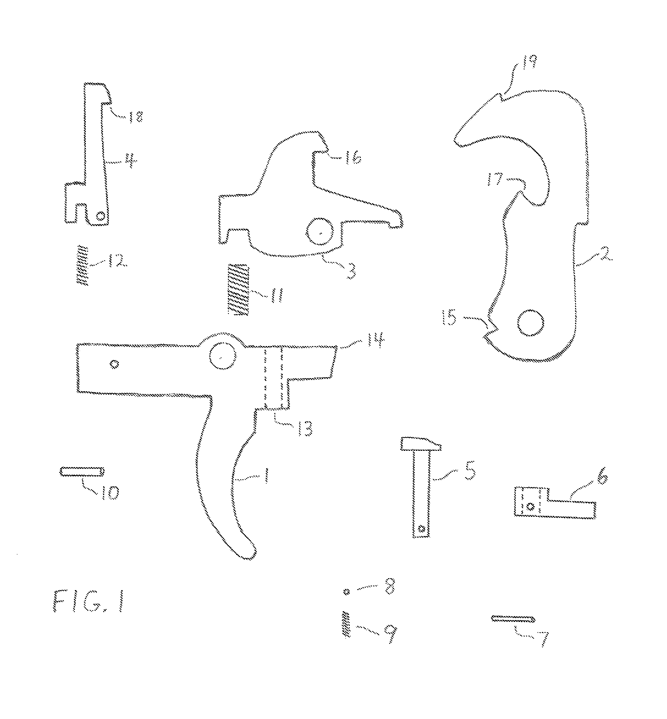
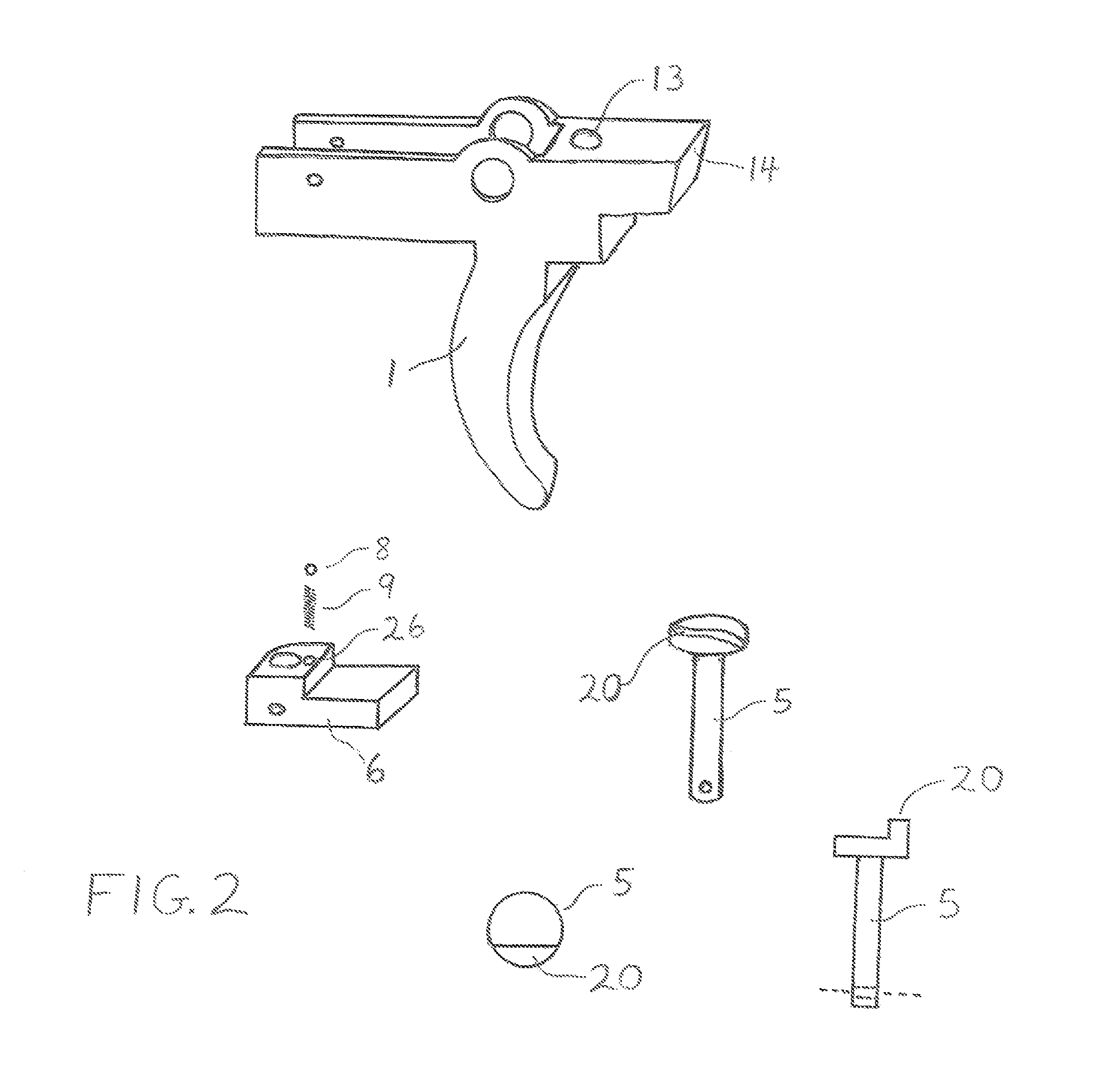
[0063]The core components of the selectable dual mode trigger are illustrated in FIG. 1. A trigger 1 is manufactured with a selector cam bore 13 in which a selector cam 5 fits, with its shaft protruding from the bottom of the trigger 1.

[0064]Affixed to the lower portion of selector cam 5 by means of a selector pin 7 is a selector lever 6. A selector detent 8 and a selector detent spring 9 fit inside the selector lever 6. The trigger 1 has a slot in its top portion to fit a primary disconnector 3, a primary disconnector spring 11, a secondary disconnector 4, and a secondary disconnector spring 12. A secondary disconnector pin ...


PUM


Abstract

One embodiment of a trigger system with an integral selector for semi-automatic firearms. A selector allows the user to choose between two modes and rates of fire. A trigger (1) is made to allow passage of the lower portion of a selector cam (5) to the exterior of the firearm. A selector lever (6) is affixed to the lower end of the selector cam (5) on the exterior of the firearms action. Turning the selector lever (6) rotates the selector cam (5) which tilts a pivotal disconnector (3) on its axis, varying the amount of disconnector (3) engagement with a hammer (2). The variance in the disconnector (3) engagement causes the firearm to fire in one of two modes, firing one round with a trigger pull and resetting with trigger release, or firing one round with trigger pull, and firing another round with trigger release. Other embodiments are described.

Description

CROSS-REFERENCE TO RELATED APPLICATIONS[0001]This application claims the benefit of nonprovisional patent application Ser. No. 13 / 714,453 filed 2012 Dec. 14 by the present inventor.BACKGROUNDPrior Art[0002]The following is a tabulation of some prior art that presently appears relevant:[0003]U.S. patentspatent No.Issue DatePatentee4,344,351Aug. 17, 1982McQueen4,514,923May 7, 1985Teel4,685,379Aug. 11, 1987Troncoso4,787,288Nov. 29, 1988Miller5,074,190Dec. 24, 1991Troncoso6,101,918Aug. 15, 2000Akins6,966,138Nov. 22, 2005Deckard[0004]Semi-automatic firearms have a limited firing rate as compared to automatic weapons. Automatic weapons are also known to be prohibitively expensive and harder to acquire than semi-automatic firearms. As a result many devices have been proposed in the past for increasing the firing rate of semi-automatic firearms. See for example, U.S. Pat. No. 4,344,351 to McQueen; U.S. Pat. No. 4,787,288 to Miller; U.S. Pat. Nos. 4,803,910 and 5,074,190 to Troncoso; U.S. Pa...

Claims


Application Information

Patent Timeline
Patent Type & Authority Patents(United States)
IPC IPC(8): F41A19/00
CPCF41A19/45F41A19/46
Inventor HAWBAKER, PETER, JONATHAN
Owner FOSTECH INC
Why Eureka
Try Eureka