Land roller

a technology of land rollers and implements, applied in the field of land rollers, can solve the problems of increasing the mass and size of the wings, unable to move, and shortening the beams of heavy beams

Active Publication Date: 2014-09-02
AG SHIELD LTD
View PDF2 Cites 16 Cited by
  • Summary
  • Abstract
  • Description
  • Claims
  • Application Information

AI Technical Summary

Benefits of technology

[0020]By providing a transport wheel which is aligned with the gap between a plurality of rollers in series, and which is pivotal into a working position from a transport position, a single wheel can provide both functions of supporting the rollers for transport as well as packing the gap between a plurality of rollers connected in series. The connection of the rollers in series minimizes the width of the implement in the transport position.
[0033]By further providing a drive motor arranged to drive a drive wheel at the outer ends of the wings, the wings can be driven forward from the transport position to the forward working position without the implement being displaced either forwardly or rearwardly across the ground. A large land roller implement with a narrow transport width is thus readily adaptable for use with a series of implements unlike any prior art device. By further providing a motor output which only engages the wheel in the working position, the motor is arranged to automatically disengage contact with the drive wheel in the transport position such that the wheel is free rolling when being towed in the transport position.
[0053]The vertical movement between the inner end of the wings and the central frame allows land packer rollers on the wings to be supported at a different elevations than a land packer roller on the central frame while the rollers remain substantially parallel to one another and the ground so that the implement is better able to follow contours of the ground.
[0072]By supporting a leveling beam ahead of each roller in which the beam suspension independently supports the beam on the frame of the roller, a floating beam is provided which levels protruding mounds of soil ahead of the compaction of the roller while readily permitting the beam to be deflected relative to the roller when obstacles are encountered. By further providing a plurality of support rollers along the rear side of the beam, the beam can be supported for upward and rearward movement into rolling engagement with the main packing roller to provide additional support to the beam when obstacles are encountered. A longer and more lightweight beam can thus be used for leveling than prior art attempts while remaining well supported against damage from contacting obstacles due to the support rollers being arranged for rolling engagement with the main packing roller. By arranging the beam suspension to bias the beam and support rollers into a forward position ahead of the main packing roller, the support rollers are protected from excessive wear as the support rollers are not in rolling engagement during normal operation. Normal operation typically comprises low load operation where the beam is working light soil or the beam encounters few mounds or stones. The biasing of the spring is intended to be overcome so that the support rollers engage the packing roller under non-typical high load loading of the beam resulting from contact with an excessive number of hard packed mounds or large stones for example.

Problems solved by technology

Due to the rollers being in line with one another, a gap is provided between adjacent rollers requiring additional trailing rollers at the gaps which add to the mass and size of the wings.
Such a movement is not possible when a plurality of implements are connected in series so that one is typically limited to smaller rollers such as disclosed in Almer in such an instance.
The heavy beams are very short and only used with small rollers due to the considerable strength required to prevent damage thereof.
The resulting complexity of multiple heavy beams with release mechanisms associated therewith is very complex in construction and results in a very wide transport width due to the excess material and equipment provided.

Method used


Image

  • Land roller
  • Land roller
  • Land roller

Examples


Embodiment Construction

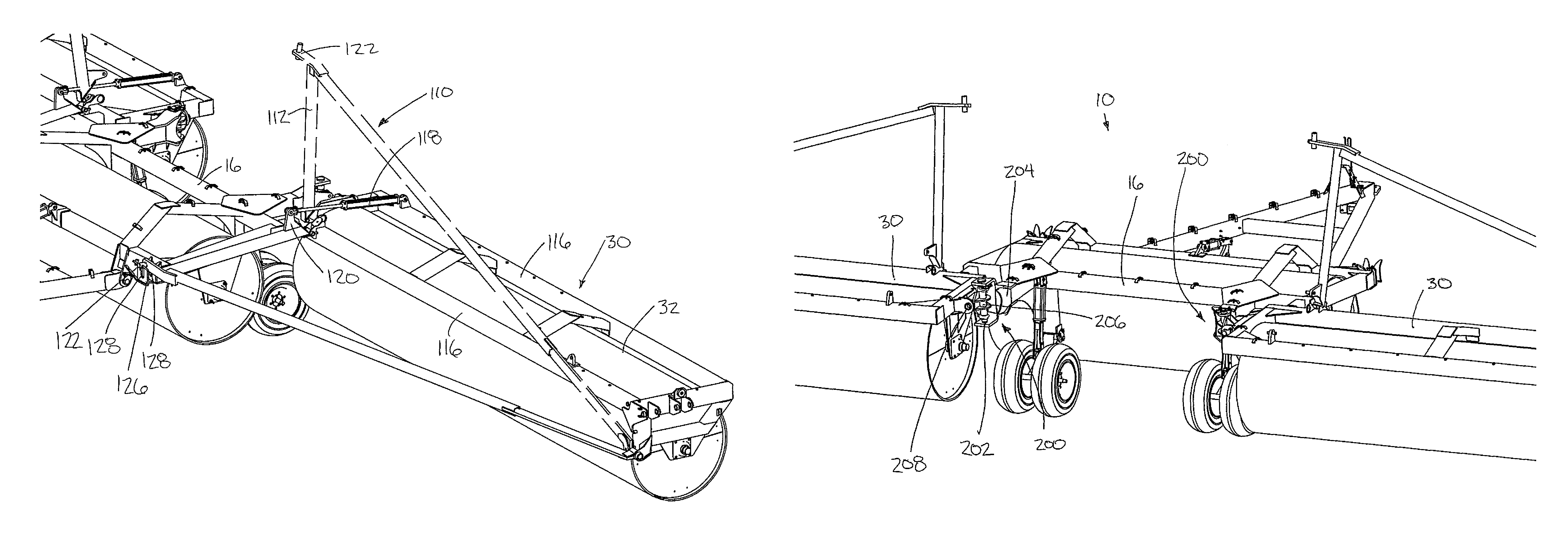
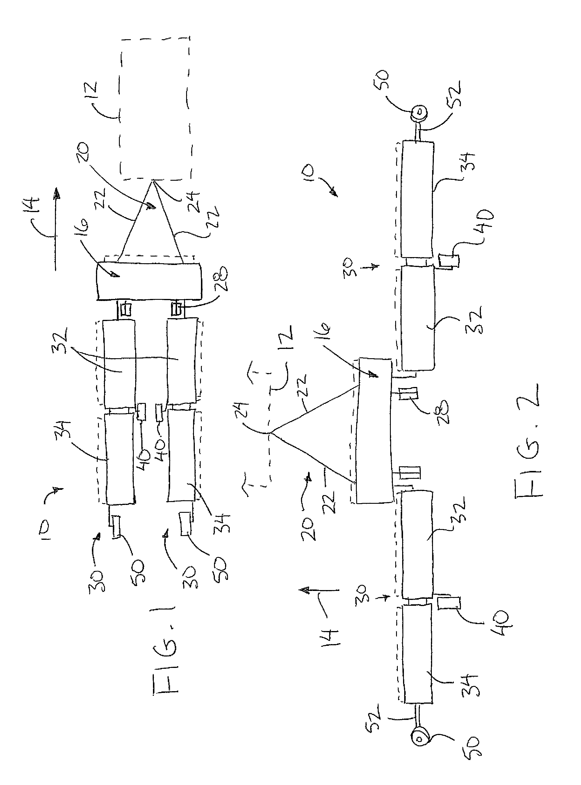
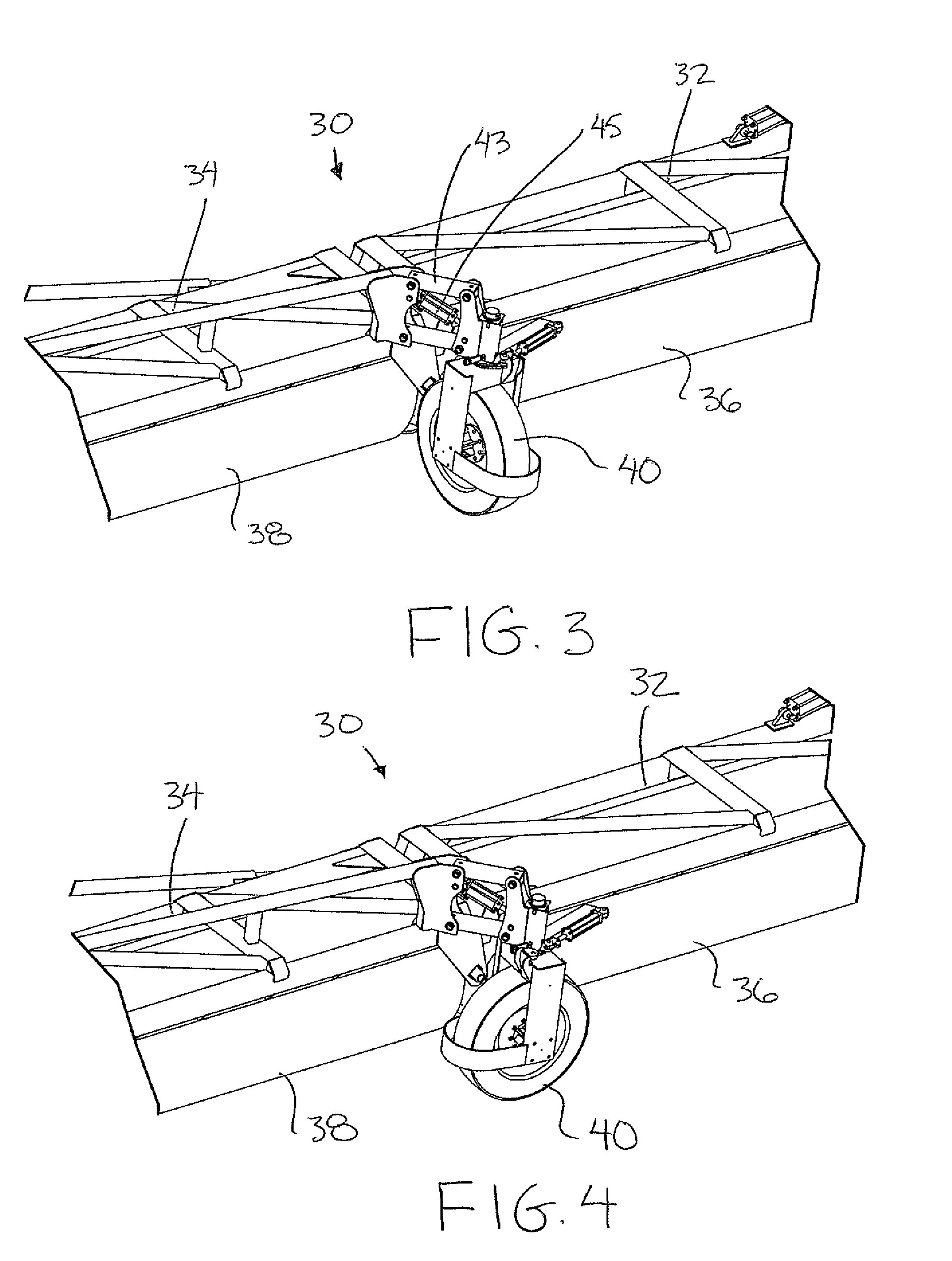
[0126]Referring to the accompanying figures there is illustrated a land roller implement generally indicated by reference numeral 10. The implement 10 is particularly suited for use with a towing vehicle, for example a tractor 12 for rolling movement across the ground in a forward working direction 14 of the tractor.

[0127]The implement 10 comprises a central frame portion 16 which is elongate in a lateral direction perpendicular to the forward working direction. The central frame includes front and rear beams 18 spanning the width of the frame and interconnected by suitable crossbars.

[0128]A hitch member 20 is coupled to the front of the central frame portion 16. The hitch member generally comprises two arms 22 which are hinged at rear ends on the front beam of the central frame portion and which extend forwardly and inwardly to be joined at a front end locating a suitable coupling 24 for connection to the towing vehicle.

[0129]The central frame portion 16 supports a central roller 2...


PUM


Abstract

A land roller implement includes a wheel aligned with the respective gap between the inner roller and the outer roller of each wing in which the wheel is pivotal between a packing position in the working position of the rollers and a transport position supporting the rollers in the transport position of the implement. The wings can also include a drive motor associated with each transport wheel to drive forward rotation of the wheel for displacing the wings from the transport position to the working position without displacing the implement in a rearward direction. A leveling beam attachment and a seeding attachment can also optionally be used on the land roller implement. Optional latchable brace members pivotally supported on the wings may provide additional support to the wings when using the leveling beam attachment.

Description

[0001]This application claims the benefit under 35 U.S.C. 119(e) of U.S. provisional application Ser. No. 61 / 258,092, filed Nov. 4, 2009 and U.S. provisional application Ser. No. 61 / 296,190, filed Jan. 19, 2010.FIELD OF THE INVENTION[0002]The present invention relates to an agricultural land roller implement of the type comprising a plurality of rollers arranged to be towed in a forward working direction by a towing vehicle, for example an implement comprising a centre section with a central roller and a pair of wings with additional rollers in which the wings are arranged to be displaced between a forward working position and a trailing transport position. The present invention also relates to improvements to a land roller including a ground leveling device ahead of the rollers and a cover crop roller device arranged for selective attachment to the rollers.BACKGROUND[0003]Land rollers are used for soil compaction and terrain flattening in various applications, including agriculture...

Claims


Application Information

Patent Timeline
Patent Type & Authority Patents(United States)
IPC IPC(8): A01B73/06A01B29/06A01B49/06A01B63/32A01B29/02
CPCA01B63/32A01B73/067A01B49/06A01B29/02A01B63/22A01B69/00A01C5/068
Inventor MCCREA, DAVID GARYMCCREA, THOMAS EDWARD
Owner AG SHIELD LTD
Why Eureka
Try Eureka