Headrest for motor vehicle seat

Active Publication Date: 2014-09-02
FAURECIA
View PDF9 Cites 0 Cited by
  • Summary
  • Abstract
  • Description
  • Claims
  • Application Information

AI Technical Summary

Benefits of technology

The present invention aims to provide a system for assembling spindles in the body of a headrest that overcomes the shortcomings of conventional systems. Specifically, the invention aims to avoid the use of force-fit pins to lock spindles in the headrest body, to enable easier detection of incorrect assembly, and to provide a more efficient and effective means of assembling spindles.

Problems solved by technology

A disadvantage of such an assembly is that it requires for an operator to force fit the two locking pins.
A disadvantage is that in case of an incorrect fastening, the plastic frame is damaged and can no longer be used.

Method used


Image

  • Headrest for motor vehicle seat
  • Headrest for motor vehicle seat
  • Headrest for motor vehicle seat

Examples


Embodiment Construction

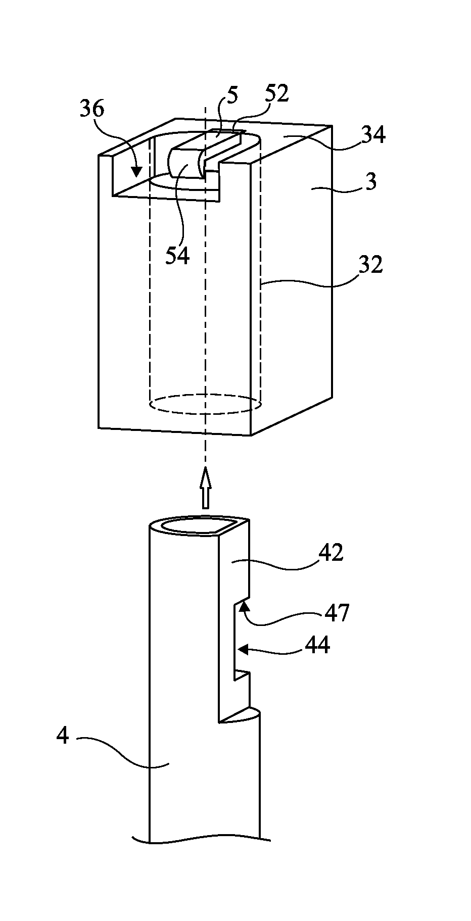
[0043]The same elements have been designated with the same reference numerals in the different drawings. For clarity, only those elements which are useful to the understanding of the present invention have been shown and will be described. In particular, the manufacturing of the spindles and of the head for receiving them has not been detailed, the present invention being compatible with usual methods for manufacturing metal spindles and plastic frames or the same in other materials. Further, the upholstery of the headrest has not been detailed either, the present invention being here again compatible with upholsteries currently associated with such headrests.

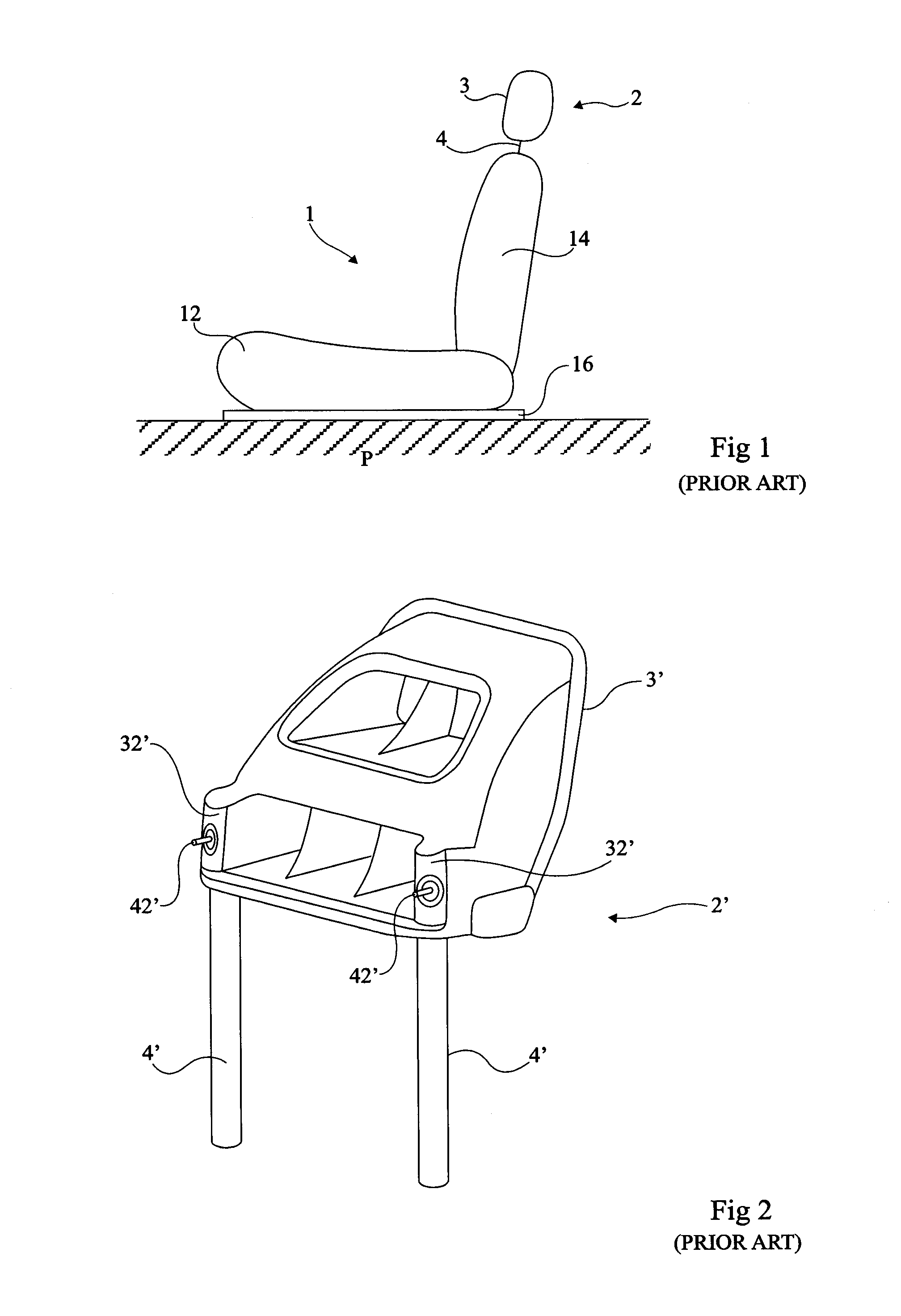
[0044]Reference will be made to terms front, back, bottom, top, upper, lower, etc., considering a headrest in a normal position of installation on a vehicle seat (for example, such as illustrated in FIG. 1).

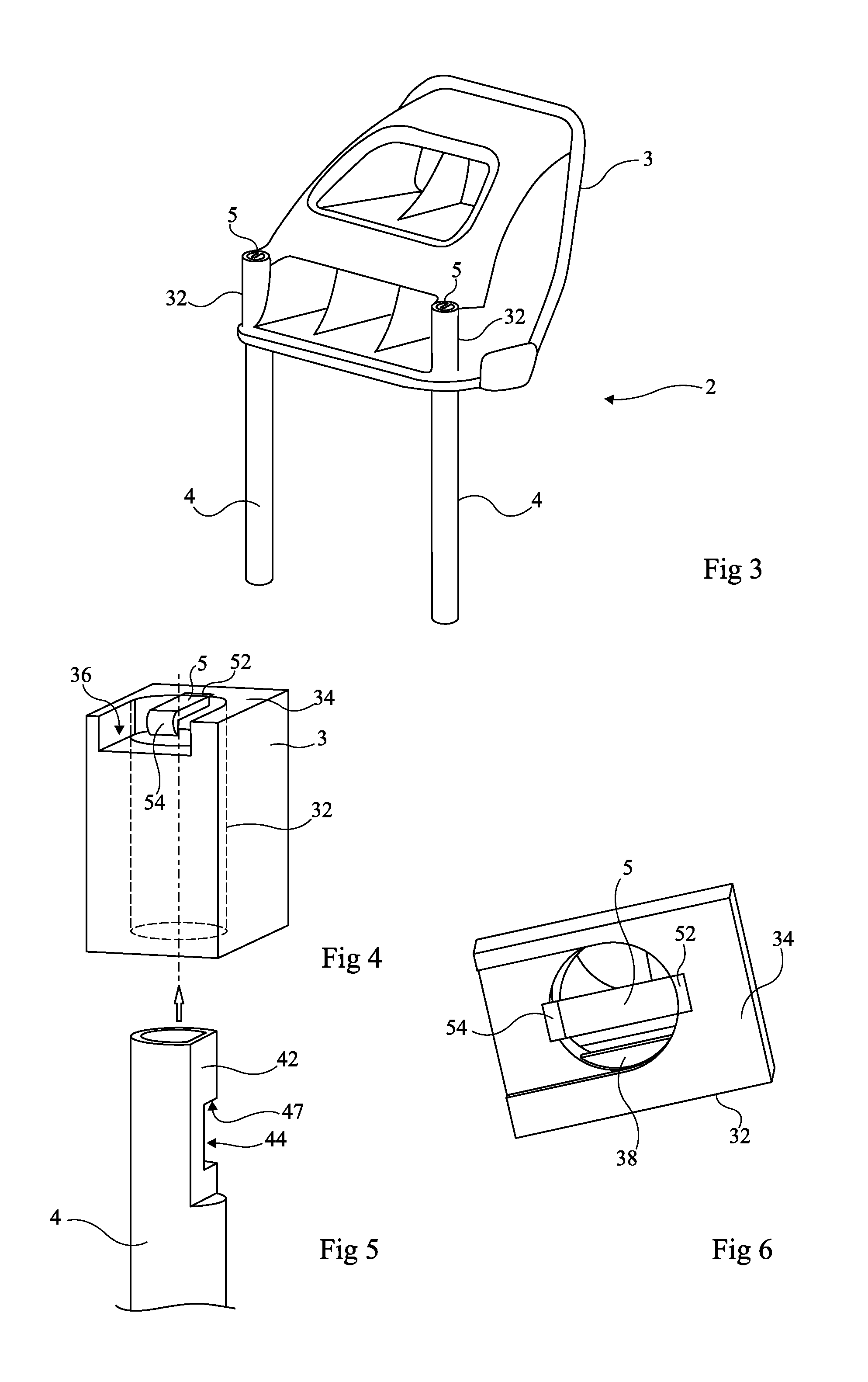
[0045]FIG. 3 is a rear perspective view of a headrest 2 according to an embodiment of the invention.

[0046]As previously, t...


PUM


Abstract

A headrest for a motor vehicle seat comprises at least one spindle for assembling the headrest in a backrest of the seat; and a body provided with at least one housing in the shape of a sleeve for receiving one end of said spindle, the spindle comprising, in an upper portion, a shoulder capable of cooperating with a horizontal rib, protruding inside of a housing of the body, to lock any translation of the spindle in its housing.

Description

BACKGROUND OF THE INVENTION[0001]1. Field of the Invention[0002]The present invention generally relates to motor vehicle seats and, more specifically, to the forming of a headrest for such seats.[0003]2. Discussion of Prior Art[0004]Different types of headrests for motor vehicle seats are known. Two types of headrests can be mentioned, those integrating an adjustment mechanism and simpler ones for which the position of a body of the headrest with respect to spindles engaged in the backrest of the seat is fixed. In the first category, the spindles generally form the two branches of a U having its base fastened to a frame of the headrest. In the second category, to which the present invention more specifically applies, the spindles are formed of metal rods which are individually connected to the headrest frame. The body or frame of the headrest then more and more often is a plastic frame or case having sleeves into which the spindles are engaged. In all cases, the frame is subsequentl...

Claims


Application Information

Patent Timeline
IPC IPC(8): B60N2/48B60N2/90
CPCB60N2/4802B60N2/441B60N2/4808Y10T29/49826B60N2/803B60N2/809B60N2/91
Inventor CHARLES, PHILIPPE
Owner FAURECIA
Why Eureka
Try Eureka