Integrally bladed rotor disk for a turbine

a turbine and rotor disk technology, applied in the field of thermodynamics, can solve the problems of circumferential measurement spacing, possible or not easily possible, and the flow of cooling air between the shafts of the rotor blades, so as to improve the control of the cooling air stream, prevent or reduce the flow of cooling air, and the effect of small complexity

Inactive Publication Date: 2014-09-02
MTU AERO ENGINES GMBH
View PDF16 Cites 9 Cited by
  • Summary
  • Abstract
  • Description
  • Claims
  • Application Information

AI Technical Summary

Benefits of technology

[0007]The present invention is based on the idea of creating a sealing device on an integrally bladed rotor disk for a turbine in order to prevent or reduce the extent to which cooling air is able to flow from a high-pressure side of the rotor disk through openings to a low-pressure side. This sealing device may partially or completely seal, in particular, annularly configured openings between shafts of adjacent rotor blades in each case. Thus, it is possible to prevent or reduce the extent to which cooling air is able to flow from the high-pressure side to the low-pressure side of the rotor disk, even in the case of shafts having a substantial length measured in the radial direction and / or a substantial spacing therebetween measured circumferentially.
[0008]The present invention creates additional degrees of design freedom, thereby making it possible to further optimize the integrally bladed rotor disk and the manufacturing thereof. For example, the shafts may have a narrower design, thereby improving an inflow of cooling air to the entry orifices of inner cooling channels that are configured at the sides of the shafts.
[0014]In the context of platforms that are not welded together, it is also an underlying idea of the present invention to configure sealing devices between the shafts of the rotor blades and in such a way that they adjoin the platforms, in particular, radially inwardly. These sealing devices make it possible to prevent or reduce a gas stream in the radial direction in between the platforms of adjacent rotor blades. It is especially possible to prevent or reduce a flowing of cooling air from the openings or interspaces between the shafts of the rotor blades radially outwardly to the blades, as well as an entry of hot gases radially inwardly. Since the sealing devices are configured between the shafts and in such a way that they adjoin the platforms, little complexity is entailed in inserting the same following connection of the rotor blades to the central disk element. The sealing action may be reinforced by the centrifugal forces acting during operation of the turbine that press the sealing devices against the platforms. It is possible to advantageously combine the above described sealing device for sealing the openings between the shafts of the rotor blades against a mass flow in the axial direction with the last-described sealing devices for sealing against a mass flow in the radial direction. It is thus possible to provide an almost complete control of the cooling air streams that would otherwise only be possible if the rotor disk were completely enclosed within the platform(s). For this purpose, other sealing devices may also be used for sealing in the radial direction.
[0015]Overall, therefore, in its various forms and specific embodiments, the present invention makes possible an improved control of the cooling air stream and less loss of cooling air. It is thus possible to realize a reduced cooling air requirement and / or an improved cooling of the rotor disk, including the central disk element and the rotor blades. The present invention is suited for turbines, in particular for extreme temperature-exposed high-pressure turbines or high-pressure components of turbines, in jet engines, turbofan engines, turboprop engines, turboshaft engines and other engines of airplanes or other vehicles, as well as in stationary applications.

Problems solved by technology

Since a number of disadvantages are entailed in manufacturing an integrally bladed rotor disk from one piece, the rotor blades are normally manufactured individually and then joined in an integral metallurgical bond to a disk element by friction welding or some other method.
The rotor disk described in U.S. Patent Application 2005 / 0232780 A1 has the inherent disadvantage that cooling air can flow through between the shafts of the rotor blades, from the high-pressure side to the low-pressure side of the rotor disk.
Due to reasons related to production engineering, in certain manufacturing processes, it is not possible or not easily possible to have circumferentially measured spacing intervals between the shafts whose widths are below a minimum value.

Method used


Image

  • Integrally bladed rotor disk for a turbine
  • Integrally bladed rotor disk for a turbine
  • Integrally bladed rotor disk for a turbine

Examples


Embodiment Construction

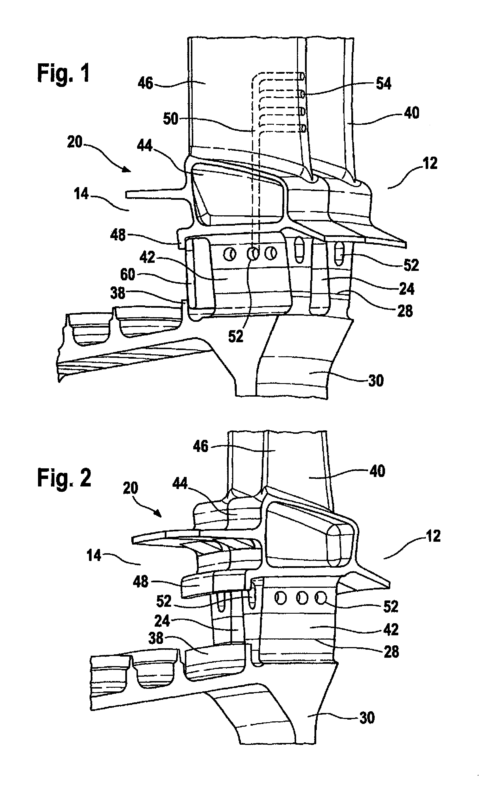
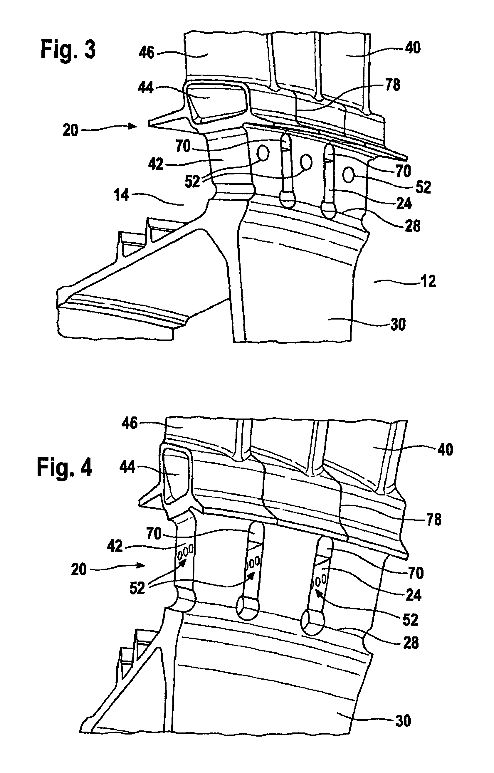
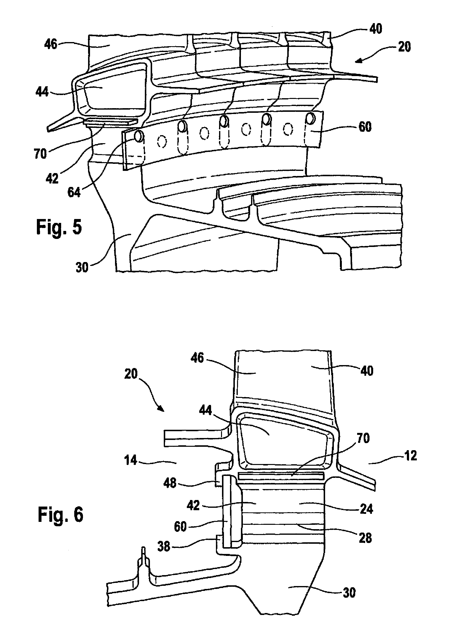
[0028]The figures described in the following show schematic representations of various specific embodiments of integrally bladed rotor disks. In each case, only one section of the rotor disk is shown, namely a radially outer region of a section of a disk element, to whose outer periphery, rotor blade shafts of a rotor blade ring are joined in a substance-to-substance bond. The rotor blades, in particular the blades thereof, are also only partially shown. Some of the figures show cylinders that are attached to the actual rotor disks and may be formed in one piece therewith, but are not discussed in greater detail in the following. FIG. 1 through 7 and 9 show perspective representations; FIGS. 8 and 11 show sections along a plane that includes the axis of the rotor disk. FIG. 1 shows an integrally bladed rotor disk 20 having a disk element 30 that is joined in a substance-to-substance bond in an outer region to rotor blades 40. Each rotor blade has a shaft 42, a platform 44 and a blad...


PUM


Abstract

An integrally bladed rotor disk (20) for a turbine, including rotor blades (40), which are joined in a substance-to-substance bond to a disk element (30), and a sealing device (60) for preventing or reducing the extent to which cooling air is able to flow from a high-pressure side (12) of the rotor disk (20) through openings (24) on the rotor disk (20) to a low-pressure side (14) of the rotor disk (20).

Description

[0001]The present invention relates to an integrally bladed rotor disk (blisk=bladed disk) for a turbine, in particular for a high-pressure section of a turbine, as well as to a turbine.BACKGROUND[0002]Due to thermodynamics, the efficiency of an internal combustion engine increases with the combustion temperature. Therefore, for gas turbines used in numerous variants in aircraft, but also in other vehicles and in stationary applications, one aspires to ever higher temperatures in the combustion chamber(s). In the high-pressure section of the turbine directly downstream of the combustion chamber(s), all open surfaces of guide vanes and rotor blades and other exposed components are subject to these high temperatures. To be able to operate a turbine at a highest possible temperature, the components, in particular the blades, which are exposed to the hot gas stream, are cooled by interior cooling channels and by a film cooling.[0003]Integrally bladed rotor disks have been developed for ...

Claims


Application Information

Patent Timeline
Patent Type & Authority Patents(United States)
IPC IPC(8): F01D5/18F01D5/34
CPCF01D5/34F01D5/082Y02T50/676Y02T50/60
Inventor BORUFKA, HANS-PETERSTIEHLER, FRANKARRIETA, HERNAN VICTORPROKOPCZUK, PATRICKLORENZ, JOACHIM
Owner MTU AERO ENGINES GMBH
Why Eureka
Try Eureka